Page 2 of 3
Re: PIC24FJxxGB002 and GA002
Posted: Fri Feb 26, 2021 5:33 pm
by p.erasmus
HI
I did not check that the device really runs at the correct frequency as I supposed you check that with a blinking led ( also do not have such an device guessing at the moment)
I modified what I think it should be for 10Khz on PWM1 with Timer 1,I load a fix value of around 50% Duty cycle in the PWM1 call(macro)
Just as a information on the dsPIC and PIC24 devices if your timer period is for example 400 cycle to achieve the Frequency you want then the duty cycle you have to set is 400 = 100% 200 = 50% and 25% = 100 and so on .if these things does not match then there is no PWM output (in general) try this PWM1 and let us see where we are standing

Re: PIC24FJxxGB002 and GA002
Posted: Fri Feb 26, 2021 6:26 pm
by alanwms
Not sure what the "rar" file is - But the PWM works perfectly when assigned to RB3. Assigning to RB7, RB8, or RB9 fails to produce a signal
Re: PIC24FJxxGB002 and GA002
Posted: Fri Feb 26, 2021 6:29 pm
by p.erasmus
It just a zip file ,ok that sound good then I suppose Ben needs to look at the Remap pins
Re: PIC24FJxxGB002 and GA002
Posted: Fri Feb 26, 2021 6:45 pm
by alanwms
Ben - Can you ressurent this issue? Let me know if the remap software is working correctly. My project is getting a little tedious.
Re: PIC24FJxxGB002 and GA002
Posted: Mon Mar 01, 2021 11:58 am
by BenR
Hello,
I've had a good poke around in the datasheet and looked at the remap registers and values being passed by Flowcode and so far it all appears to be correct.
You said this.
found that I can get pin 7 to produce the PWM when I assign to that pin, but not the others.
and then said this.
the PWM works perfectly when assigned to RB3. Assigning to RB7, RB8, or RB9 fails to produce a signal
The remap must be at least partially working as all outputs are by default set to null output.
If you create a simple program with a single PWM output which pins / timers are working. If you can somehow narow down the problem to a timer setting or pin setting then that might help.
If you look at the generated C code then you can see the PWM remap values being generated. Here is PWM channel 1.
Code: Select all
/*========================================================================*\
   Use :cal_pwm
       :Variable declarations
       :Macro function declarations
\*========================================================================*/
#define MX_PWM_REF1
#define MX_PWM_PRESCALE1 (1)
#define MX_PWM_PIN_1 (3)
#define MX_PWM_TYPE_1 (0)
#define MX_PWM_PORT_1 PORTB
#define MX_PWM_TRIS_1 TRISB
#define MX_PWM_CHANNEL_1 (1)


/*=----------------------------------------------------------------------=*\
   Use :cal_pwm
       :Supplementary defines
\*=----------------------------------------------------------------------=*/
#define MX_PWM
#define MX_PWM_REMAPPABLE
#define MX_PWM_RPOR_1 RPOR1bits.RP3R
#define MX_PWM_RPOC_1 18
#define MX_PWM_OCxCON
#define MX_PWM_TMR_1 1
These are the lines that handle the remapping.
#define MX_PWM_RPOR_1 RPOR1bits.RP3R
#define MX_PWM_RPOC_1 18
Here are the PWM channels
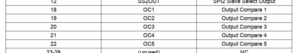
- RP_OC.jpg (31.35 KiB) Viewed 7640 times
Here are the output register bits, showing RP2R and RP3R inside register RPOR1.
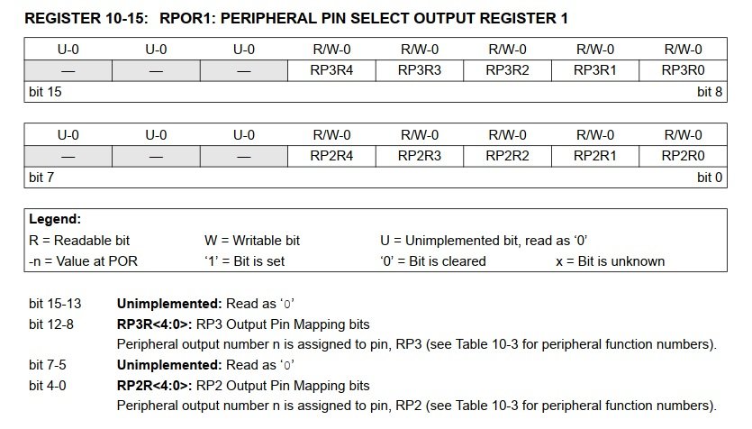
- RP_REG.jpg (84.05 KiB) Viewed 7640 times
And finally the RP pin assignment
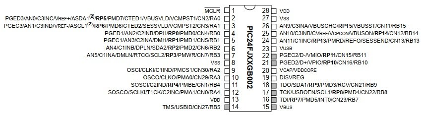
- RP_PIN.jpg (57.04 KiB) Viewed 7640 times
Hopefully with a simple test we can get to the bottom of what's going wrong for you.
Could it be something simple like opens or shorts on your PCB? Can you confirm with a multimeter.
Re: PIC24FJxxGB002 and GA002
Posted: Mon Mar 01, 2021 1:52 pm
by alanwms
Thanks Ben - In reading the data sheet - It discusses a requirement to write the remap code in assembly due to speed requirements. Is that something to consider?
I will take another look at the hardware and see if anything is wrong.
Re: PIC24FJxxGB002 and GA002
Posted: Mon Mar 01, 2021 9:00 pm
by alanwms
I have the PWM channels working - I don't know why, but they are running. Some of my Analogs are not running. Could you take a quick look and see what I am doing wrong Ben?
The analog readings for AN9, 10 and 11 are reading zero - I have measured them on the pic, and they do have voltages.
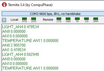
- Zeros Analogs.jpg (21.6 KiB) Viewed 7634 times
Re: PIC24FJxxGB002 and GA002
Posted: Wed Mar 03, 2021 3:00 pm
by BenR
Hi Alan,
Sorry please can you post your .fcfx project file and I will investigate for you.
Re: PIC24FJxxGB002 and GA002
Posted: Wed Mar 03, 2021 6:56 pm
by alanwms
here it is - Work in progress- Only concerned with AN9,10, and 11 which are not responding. I have applied 1.5 volts to each individual pin and see no numbers. The AN4 is not working but that is to be expected - According to the datasheet, it is not available. I will be trading pins on that one.
Thanks Ben
Re: PIC24FJxxGB002 and GA002
Posted: Mon Mar 08, 2021 10:28 pm
by BenR
Thanks Alan,
Looking now...
Edit, I've found a problem with the ADC definitions for the GB002 / GB004 family and hopefully with the latest updates things should be working correctly for you.
Let me know how you get on.
The AN4 is not working but that is to be expected - According to the datasheet, it is not available. I will be trading pins on that one.
I didn't see any problems with AN4 while looking through things so hopefully this one will work ok for you now too.