Page 1 of 1
Interfacing flowcode program on adruino BL0055 eblock2 board
Posted: Wed Mar 15, 2023 10:49 pm
by Oluwatobiloba0000
I'm working on a CAN Bus communication with eblock2 but I've been having several issues and they are listed below
1 : recognition of the ardruino port and bl0055 eblock2 usb on my pc device manager : I found the link below on how to set it up but after downloading the drivers, I couldn't find on my device manager
https://www.matrixtsl.com/faq/index.php ... artlang=en
2. How to upload each programs on each CAN nodes using flowcode
Re: Interfacing flowcode program on adruino BL0055 eblock2 board
Posted: Thu Mar 16, 2023 10:49 am
by medelec35
Hello.
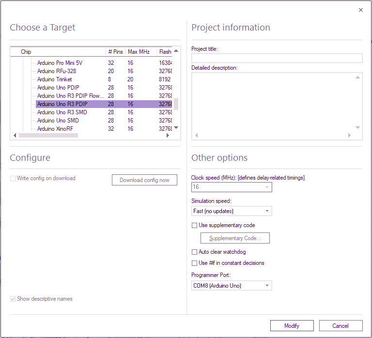
With only the Arduino Uno connected to the PC via USB
If you select
Build >
Project options, you should have something like this:

- Using Ardunio Shield..png (46.73 KiB) Viewed 6740 times
Re: Interfacing flowcode program on adruino BL0055 eblock2 board
Posted: Thu Mar 16, 2023 1:33 pm
by Oluwatobiloba0000
From the device manager. The USB isn't recognised as it can be seen in the picture attached to this message. Does it matter? How do I go about it if it matters. Thanks
Re: Interfacing flowcode program on adruino BL0055 eblock2 board
Posted: Thu Mar 16, 2023 2:28 pm
by medelec35
Hello.
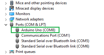
Yes, it's vital that when you plug in the Arduino, a VCP (Virtual Com Port) is automatically set up like this:

- Arduino VCP.png (11 KiB) Viewed 6724 times
For that to happen you must have the correct drivers installed.
Some Uno's will work straight away as windows will have the correct drivers by default e.g. Dip version
For other Uno's e.g the SMD version, you will have to manually add the drivers.
I believe it's the CH340 drivers.
I have attached the drivers for you to try.
Re: Interfacing flowcode program on adruino BL0055 eblock2 board
Posted: Wed Mar 22, 2023 10:26 am
by medelec35
Hello.
Are you able to program the Arduino Uno now?
Re: Interfacing flowcode program on adruino BL0055 eblock2 board
Posted: Tue Apr 04, 2023 8:26 pm
by Oluwatobiloba0000
From the given example on the can training material like the braking system, how can I navigate through the project manager to see how each connection is made with the eblocks(nodes), how the pins are selected and the variables to be able to relate all that with the flowchart.
Thanks
Re: Interfacing flowcode program on adruino BL0055 eblock2 board
Posted: Wed Apr 05, 2023 10:04 am
by BenR
Hello,
You probably want the properties window, using the drop down list at the top of the properties window you can select the various components in the project and look at their properties such as pin connections.
Re: Interfacing flowcode program on adruino BL0055 eblock2 board
Posted: Wed Apr 12, 2023 6:18 am
by Oluwatobiloba0000
Node 1= lcd( dashboard display)
Node 2 = switch(brake)
Node 3= led( brake light)
Node 4= sensor
Using these nodes to carry out a simple project where when the switch is pressed, the led turns on and also the lcd to display 'brake ON' and also the fuel gauge level when the potentiometer is tuned..
1. How do I go about the CAN ID number, message IDs,
TX and RX buffer
2. How to set masks and filters
3. How to go about configuration of each nodes
Re: Interfacing flowcode program on adruino BL0055 eblock2 board
Posted: Wed Apr 12, 2023 2:40 pm
by BenR
Hello,
This document should have all the information you need.
https://www.matrixtsl.com/resources/fil ... %20Bus.pdf
Firmware projects mentioned in the document are available here.
https://www.matrixtsl.com/resources/fil ... 0Files.zip
If your still having problems with your Arduino driver then you can install the device driver that is included with the Flowcode installation. Just right click the device in device manager and select install device driver, then select from known location. The location will probably be something like this C:\Program Files (x86)\Flowcode 9\data\Drivers\Arduino
Re: Interfacing flowcode program on adruino BL0055 eblock2 board
Posted: Mon Apr 17, 2023 1:41 pm
by Oluwatobiloba0000
I understand the examples given in the training course code. I would just appreciate the total break down of how the can properties configuration of each node is made and how each node flowchart is programmed. Let's use an elevator system for an example. The switch node will be for the number of floors, lcd node will be for the screen monitor for the floor number and also the Led node will denote the floor number. Switch 0 will be used as the door opener. A video will be helpful if it is possible. Thanks