Page 22 of 23
Re: PIC18F25K22 UART ERROR
Posted: Sat Sep 14, 2024 8:49 pm
by chipfryer27
Hi
Will definitely try if I get in. I'll use the WiKi examples modified for my chips to keep things simple, with of course CS/SS held Low.
Regards
Re: PIC18F25K22 UART ERROR
Posted: Sun Sep 15, 2024 2:08 pm
by chipfryer27
Hi
Not had much luck. I used a PIC16F18877 with internal clock but I'm getting some strange stuff on MOSI.
Can't find my documentation for the transceiver so unsure which pin is which.
I'll update when I get a chance.
Regards
Re: PIC18F25K22 UART ERROR
Posted: Sun Sep 15, 2024 8:39 pm
by chipfryer27
Hi
I was running out of time today so couldn't investigate much but I think it is component related.
The Tx example runs and provides updates via the UART port. On it I see:-
Start
0 (the failed transceiver init)
0 - 0
1 - 0
2 - 0
3 - 0
etc
This is the "count" increasing and being sent out on the SPI (then UART), with the result (0 = fail)
However monitoring the MOSI I don't see anything coming out that resembles what I should be seeing. It was ages ago I last played with these and I can't remember much about them. Anyone used the examples recently?
Regards
Re: PIC18F25K22 UART ERROR
Posted: Mon Sep 16, 2024 6:59 pm
by SILVESTROS
Hi,
Tomorrow I'll get a new pair of NRF24L01 to test the component using NRFTest example for Tx /Rx . I'll use PIC18F25K22 that I have.
In the meantime, maybe Matrix should do a check of NRF24L01 component , or should it first be confirmed that the NRF24L01 not work ?
Maybe to set another post for component error at forum?
Regards
Basil
Re: PIC18F25K22 UART ERROR
Posted: Mon Sep 16, 2024 7:01 pm
by chipfryer27
Hi
I'm hoping to have some free time tomorrow and hope to investigate further. I do need to find out reliable connection details for my module (with antenna) though.
Regards
Re: PIC18F25K22 UART ERROR
Posted: Tue Sep 17, 2024 7:00 pm
by chipfryer27
Hi
Found connection details and for ease I've designed a little breakout board which I hope to make tomorrow to continue testing. I've looked through the source code and will better understand what's happening when I try again.
Regards
Re: PIC18F25K22 UART ERROR
Posted: Tue Sep 17, 2024 7:21 pm
by SILVESTROS
Hi,
I get some new NRF24L01 ,and make some breakouts to connect transceiver to breadboard . I'll make some tests with PIC18F23K22 . i would like to know if NRF24L01 component works..For that I'll use my oscilloscope that can decode SPI data.
Many thanks in advance for your help.
Regards
Basil
Re: PIC18F25K22 UART ERROR
Posted: Tue Sep 17, 2024 8:33 pm
by chipfryer27
Hi
There are NRF24L01 and NRF24L01+ devices out there and it isn't always clear which is which. There appears to be some difference in registers but I haven't yet had time to go through things to see if any difference is significant.
I think the component is for the former.
Regards
Re: PIC18F25K22 UART ERROR
Posted: Wed Sep 18, 2024 1:55 pm
by chipfryer27
Hi
Okay, things going better (they always do if there is the prospect of beer at the end of task).
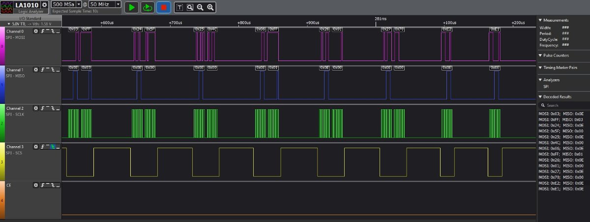
Got my connections sorted and I can now get a reply from the module. From the documentation I noticed that Data is valid on clock leading edge but my analyser had it on trailing. Obviously this makes a big difference to what is being decoded and once I set this to leading and clock low when inactive I could then get MOSI that I could "understand", by that I mean I could understand what registers were being W/R (or attempted).
I'd halted the flow at strategic points to allow me to focus in on certain commands (monitored on pins). This is initialise.

- Initialise.jpg (80.98 KiB) Viewed 4193 times
When the program loops and "counts" I don't get any confirmation on the UART:-
START
1
0 - 0
1 - 0
2 - 0
etc
No time left for today, but at least we know that the example code does communicate with the module

Regards
Re: PIC18F25K22 UART ERROR
Posted: Thu Sep 19, 2024 3:29 pm
by chipfryer27
Hi
Tried the example Rx code (changing target) and I got similar to above on my analyser. Off hand I think the only initialisation difference was flushing respective buffers, but can't say for certain as I was in a rush.
When I next get a chance I'll try and get both talking to each other.
Not certain of this as I haven't explored it very much but the "0" returns in the previous post (e.g. 1 - 0 / 2 - 0 etc) may be due to the register not containing expected values as I am using "+" modules. I may need to configure a register that at present is being left at default.
Regards