Page 1 of 2
CAN (Internal, MCP2515) Problem/Bug
Posted: Thu Jun 04, 2026 2:42 pm
by kennethnilsen69
Hi I have problems using the CAN component.
I will use both channels Internal1 and Internal2 on an ECIO40P16 (DSPIC33EP256MU806-IMR chip)
Here is the test I am doing:
http://ev-power.mine.nu/EV-POWER-NORWAY/FC/FC9_1.jpg
http://ev-power.mine.nu/EV-POWER-NORWAY/FC/FC9_2.jpg
see the attached project file
can1 works fine but can2 does not work. I need help and suspect that there is a fault/bug in the component.
I am using FC9 but get the same error in FC7
Re: CAN (Internal, MCP2515) Problem/Bug
Posted: Thu Jun 04, 2026 5:05 pm
by kennethnilsen69
Another problem is that if I initialize can2, can1 becomes very unstable and is unable to read can messages as it should.
Re: CAN (Internal, MCP2515) Problem/Bug
Posted: Thu Jun 04, 2026 8:19 pm
by kennethnilsen69
Just downloaded FC11 and same problem there
Re: CAN (Internal, MCP2515) Problem/Bug
Posted: Thu Jun 04, 2026 8:22 pm
by RGV250
Hi,
I was looking for code for a PIC24 device (not using FC) and found this which I recall the poster had a similar issue.
I have no idea how/if I can see the INIT code (which is where I think this code should be).
Anyway, this was the supposed fix, most is probably irrelevant but the bit I think might need to look at is the DMAxREQ value.
Use the same code for both modules. Switch the 1's to the 2's for the address names. For example, C1TR01CON for CAN1 becomes C2TR01CON for CAN2, etc.
Set up DMA1 for CAN transmit:
DMA1CONbits.SIZE = 0x0;
DMA1CONbits.DIR = 0x1; //From peripheral to DMA
DMA1CONbits.AMODE = 0x2;
DMA1CONbits.MODE = 0x0;
DMA1REQ = 70; <<<<<<<<<<<<<<<<<<<<<<<<< Change to 71 for CAN2
DMA1CNT = 7; //Data length
DMA1PAD = (volatile unsigned int) &C1TXD; //Point to peripheral register
DMA1STAL = (unsigned int) &CAN1MsgBuf; //Point to buffer
DMA1STAH = (unsigned int) &CAN1MsgBuf; //Point to buffer
DMA1CONbits.CHEN = 0x1; //Enable
Regards,
Bob
Re: CAN (Internal, MCP2515) Problem/Bug
Posted: Thu Jun 04, 2026 9:24 pm
by kennethnilsen69
Here is the FC11 test program attached.
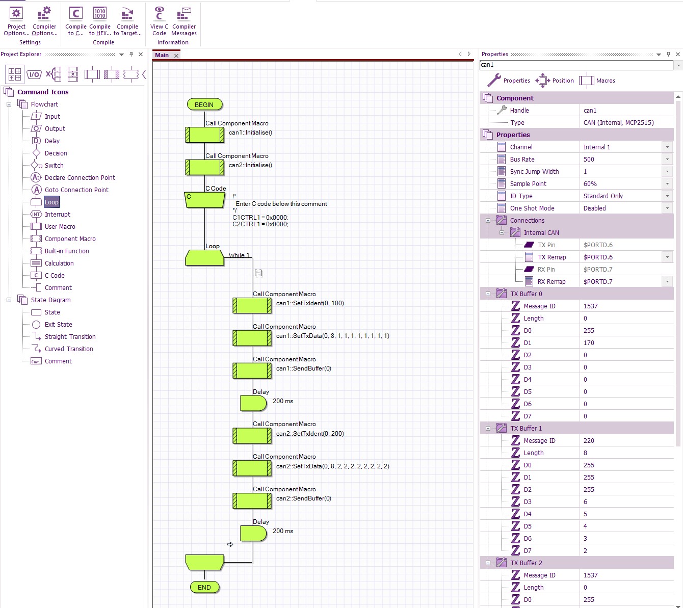
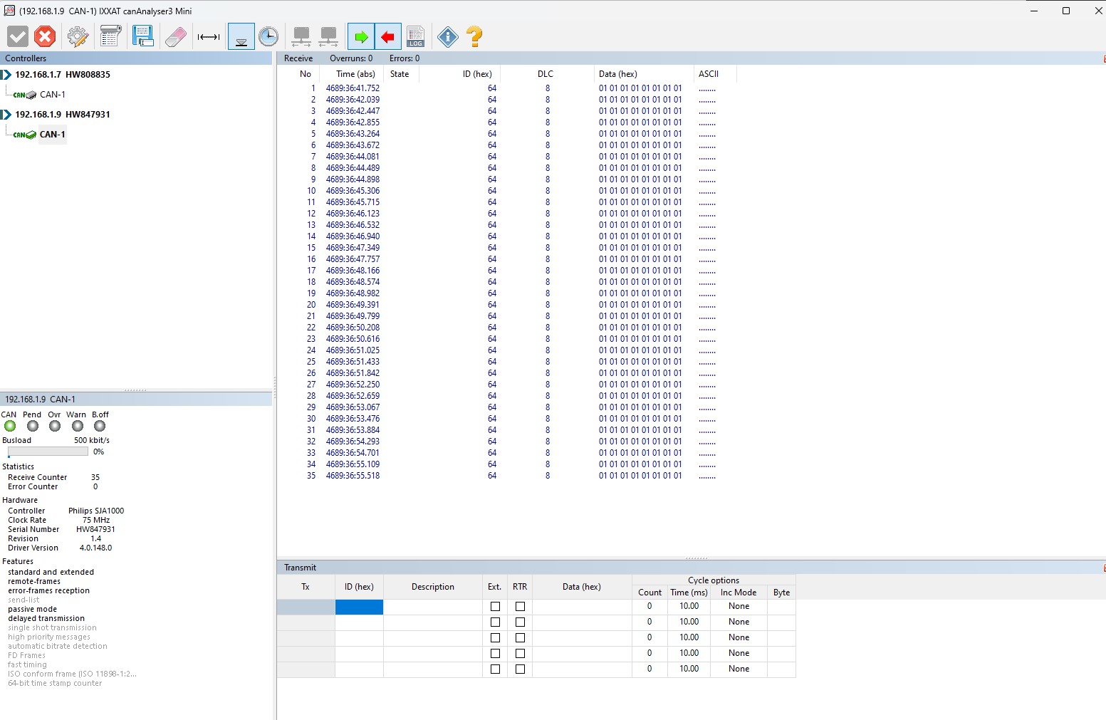
canbus1 becomes like this:
http://ev-power.mine.nu/EV-POWER-NORWAY/FC/can1.jpg
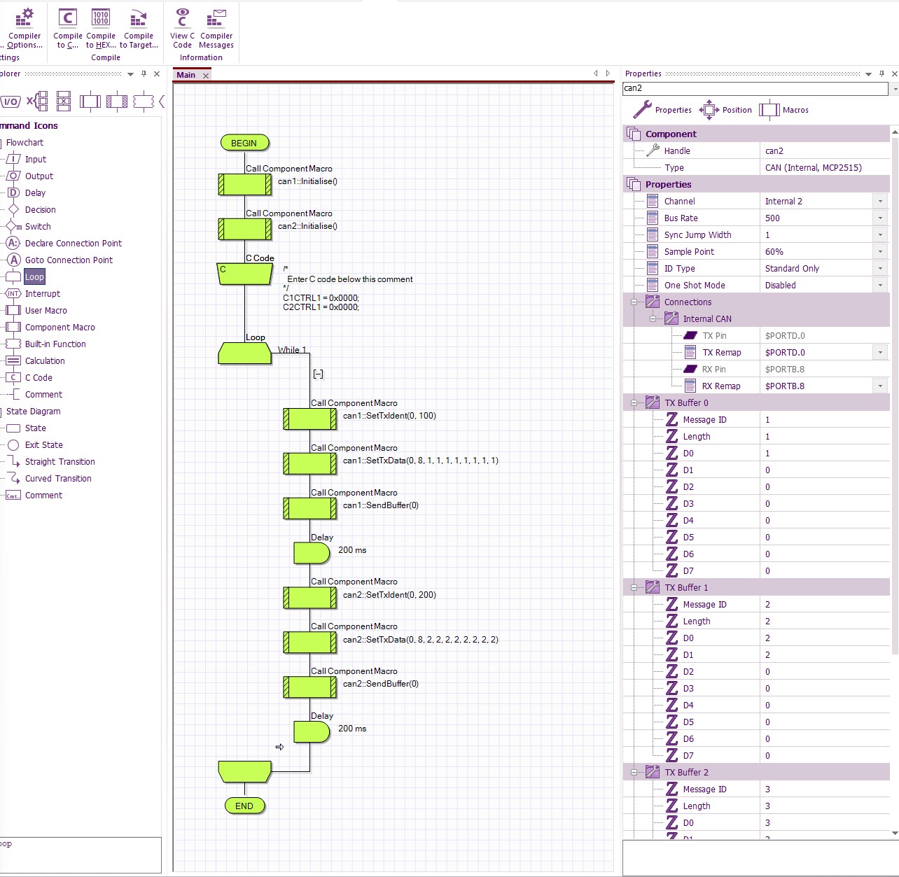
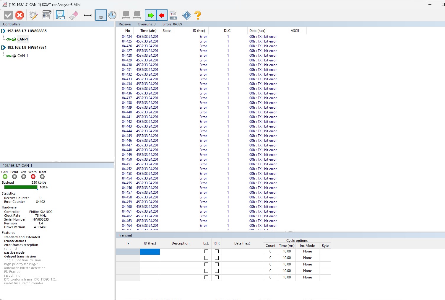
canbus2 becomes like this:
http://ev-power.mine.nu/EV-POWER-NORWAY/FC/can2.jpg
In addition, canbus1 becomes worse and more unstable at reading canbus messages on the bus when canbus2 is initialized. But sends them just fine.
Re: CAN (Internal, MCP2515) Problem/Bug
Posted: Thu Jun 04, 2026 9:33 pm
by kennethnilsen69
Thanks for the feedback Bob but I didn't understand much of it. I have no idea where to find the INIT codes in an fc project
RGV250 wrote: ↑Thu Jun 04, 2026 8:22 pm
Hi,
I was looking for code for a PIC24 device (not using FC) and found this which I recall the poster had a similar issue.
I have no idea how/if I can see the INIT code (which is where I think this code should be).
Anyway, this was the supposed fix, most is probably irrelevant but the bit I think might need to look at is the DMAxREQ value.
Use the same code for both modules. Switch the 1's to the 2's for the address names. For example, C1TR01CON for CAN1 becomes C2TR01CON for CAN2, etc.
Set up DMA1 for CAN transmit:
DMA1CONbits.SIZE = 0x0;
DMA1CONbits.DIR = 0x1; //From peripheral to DMA
DMA1CONbits.AMODE = 0x2;
DMA1CONbits.MODE = 0x0;
DMA1REQ = 70; <<<<<<<<<<<<<<<<<<<<<<<<< Change to 71 for CAN2
DMA1CNT = 7; //Data length
DMA1PAD = (volatile unsigned int) &C1TXD; //Point to peripheral register
DMA1STAL = (unsigned int) &CAN1MsgBuf; //Point to buffer
DMA1STAH = (unsigned int) &CAN1MsgBuf; //Point to buffer
DMA1CONbits.CHEN = 0x1; //Enable
Regards,
Bob
Re: CAN (Internal, MCP2515) Problem/Bug
Posted: Fri Jun 05, 2026 11:20 am
by BenR
Hi All,
In your program there doesn't seem to be any receive calls. In v11 there are interrupts for the CAN RX so might be worth trying to enable the interrupts and see if this works better and more reliable then a polling approach.
Looking at the code it looks like channel 1 and 2 are correctly specifying their own DMA.
Channel 1
Code: Select all
			// DMA0 for ECAN Xmit
			DMA0CONbits.SIZE = 0x0;
			DMA0CONbits.DIR = 0x1;
			DMA0CONbits.AMODE = 0x2;
			DMA0CONbits.MODE = 0x0;
			DMA0REQ = 70;
			DMA0CNT = 7;
			DMA0PAD = (volatile unsigned int) & C1TXD;
			#if defined (__dsPIC33E__) || defined (__PIC24E__)
				DMA0STAL = (MX_UINT32) &MX_MEMBUF_X;
				DMA0STAH = (MX_UINT32) &MX_MEMBUF_X >> 16;
			#elif defined (__dsPIC33F__) || defined (__PIC24H__)
				DMA0STA = (MX_UINT32) &MX_MEMBUF_X;
			#else
				DMA0STA = __builtin_dmaoffset(&MX_MEMBUF_X);
			#endif
			DMA0CONbits.CHEN = 0x1;

			// DMA1 for ECAN Rcv
			DMA1CONbits.SIZE = 0x0;
			DMA1CONbits.DIR = 0x0;
			DMA1CONbits.AMODE = 0x2;
			DMA1CONbits.MODE = 0x0;
			DMA1REQ = 34;
			DMA1CNT = 7;
			DMA1PAD = (volatile unsigned int) &C1RXD;
			#if defined (__dsPIC33E__) || defined (__PIC24E__)
				DMA1STAL = (MX_UINT32) &MX_MEMBUF_X;
				DMA1STAH = (MX_UINT32) &MX_MEMBUF_X >> 16;
			#elif defined (__dsPIC33F__) || defined (__PIC24H__)
				DMA0STA = (MX_UINT32) &MX_MEMBUF_X;
			#else
				DMA1STA = __builtin_dmaoffset(&MX_MEMBUF_X);
			#endif
			DMA1CONbits.CHEN = 0x1;
Channel 2
Code: Select all
			// DMA2 for ECAN Xmit
			DMA2CONbits.SIZE = 0x0;
			DMA2CONbits.DIR = 0x1;
			DMA2CONbits.AMODE = 0x2;
			DMA2CONbits.MODE = 0x0;
			DMA2REQ = 71;
			DMA2CNT = 7;
			DMA2PAD = (volatile unsigned int) & C2TXD;
			#if defined (__dsPIC33E__) || defined (__PIC24E__) || defined (__dsPIC33F__)
				DMA2STAL = (MX_UINT32) &MX_MEMBUF_X;
				DMA2STAH = (MX_UINT32) &MX_MEMBUF_X >> 16;
			#else
				DMA2STA = __builtin_dmaoffset(&MX_MEMBUF_X);
			#endif
			DMA2CONbits.CHEN = 0x1;

			// DMA3 for ECAN Rcv
			DMA3CONbits.SIZE = 0x0;
			DMA3CONbits.DIR = 0x0;
			DMA3CONbits.AMODE = 0x2;
			DMA3CONbits.MODE = 0x0;
			DMA3REQ = 55;
			DMA3CNT = 7;
			DMA3PAD = (volatile unsigned int) &C2RXD;
			#if defined (__dsPIC33E__) || defined (__PIC24E__) || defined (__dsPIC33F__)
				DMA3STAL = (MX_UINT32) &MX_MEMBUF_X;
				DMA3STAH = (MX_UINT32) &MX_MEMBUF_X >> 16;
			#else
				DMA3STA = __builtin_dmaoffset(&MX_MEMBUF_X);
			#endif
			DMA3CONbits.CHEN = 0x1;
We use a version of this code in our CAN bus trainer which has three CAN bus channels, 2 internal and 1 external so it certainly is possible to have it all working. I beleive I have an interrupt for each internal channel that collects the RX data as it happens and pops it into it's own unique circular buffer to be processed in the main loop.
Let us know how you get on with the interrupt suggestion.
Re: CAN (Internal, MCP2515) Problem/Bug
Posted: Fri Jun 05, 2026 9:32 pm
by kennethnilsen69
Hi Ben, thanks for the help, but how do I enable interrupts for the CAN RX? I can't find anything about this in can properties.
The reason I haven't set up any receive calls is just because this is a test program to get both CAN buses working

Sorry but need a little more input to understand what you mean and how I make these changes.
Where do I find these DMA codes?
Re: CAN (Internal, MCP2515) Problem/Bug
Posted: Fri Jun 05, 2026 10:54 pm
by chipfryer27
Hi
If you add an interrupt after you initialise the CAN components
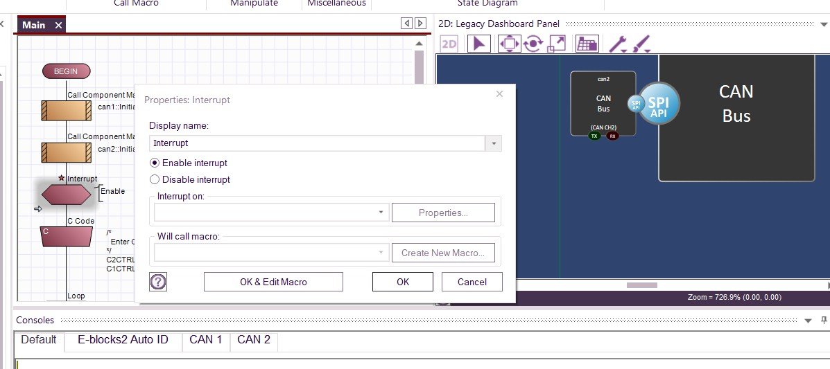
- Interrupt.jpg (100.14 KiB) Viewed 1099 times
You can then select the option you need from the drop down window
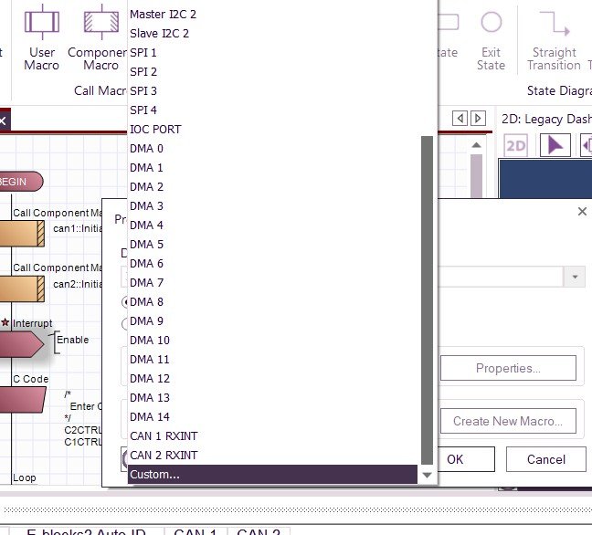
- Options.jpg (64.56 KiB) Viewed 1099 times
Hope this helps.
Re: CAN (Internal, MCP2515) Problem/Bug
Posted: Sat Jun 06, 2026 10:58 pm
by medelec35
kennethnilsen69 wrote: ↑Fri Jun 05, 2026 9:32 pm
Where do I find these DMA codes?
Hello.
If you are refeing to the code Ben posted e.g.
Code: Select all
// DMA0 for ECAN Xmit
			DMA0CONbits.SIZE = 0x0;
			DMA0CONbits.DIR = 0x1;
			DMA0CONbits.AMODE = 0x2;
			DMA0CONbits.MODE = 0x0;
			DMA0REQ = 70;
			DMA0CNT = 7;
			DMA0PAD = (volatile unsigned int) & C1TXD;
			#if defined (__dsPIC33E__) || defined (__PIC24E__)
				DMA0STAL = (MX_UINT32) &MX_MEMBUF_X;
				DMA0STAH = (MX_UINT32) &MX_MEMBUF_X >> 16;
			#elif defined (__dsPIC33F__) || defined (__PIC24H__)
				DMA0STA = (MX_UINT32) &MX_MEMBUF_X;
			#else
				DMA0STA = __builtin_dmaoffset(&MX_MEMBUF_X);
			#endif
			DMA0CONbits.CHEN = 0x1;

			// DMA1 for ECAN Rcv
			DMA1CONbits.SIZE = 0x0;
			DMA1CONbits.DIR = 0x0;
			DMA1CONbits.AMODE = 0x2;
			DMA1CONbits.MODE = 0x0;
			DMA1REQ = 34;
			DMA1CNT = 7;
			DMA1PAD = (volatile unsigned int) &C1RXD;
			#if defined (__dsPIC33E__) || defined (__PIC24E__)
				DMA1STAL = (MX_UINT32) &MX_MEMBUF_X;
				DMA1STAH = (MX_UINT32) &MX_MEMBUF_X >> 16;
			#elif defined (__dsPIC33F__) || defined (__PIC24H__)
				DMA0STA = (MX_UINT32) &MX_MEMBUF_X;
			#else
				DMA1STA = __builtin_dmaoffset(&MX_MEMBUF_X);
			#endif
			DMA1CONbits.CHEN = 0x1;
Then they can be found within the CAL_CAN.c file for your version of Flowcode and target device.
E'g for Flowcode V9 copy and paste the following within your browser as the file is hidden by default
Code: Select all
%ProgramData%\MatrixTSL\FlowcodeV9\CAL\PIC16BIT
and look for