Page 1 of 2
Thermometer project using Mikroe 7seg Click (2x 74HC595) and Mikroe Thermo 4 Click (LM75B)
Posted: Sat Jul 11, 2026 2:19 pm
by andeug
Hi,
I have been trying for a few hours to build a thermometer using the Mikroe 7seg Click and the Mikroe Thermo 4 Click, both connected to an Arduino Uno, but I cannot get it to work. What I need is to display the temperature reading from an LM75B using 74HC595 shift registers.
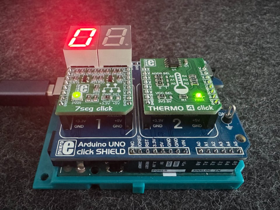
- IMG_0691.jpeg (173.94 KiB) Viewed 2948 times
I want a scenario where the first digit is omitted when the value is between 01 and 09 degrees Celsius, so the display shows only the 2nd digit.
Also, if the value exceeds 10 degrees Celsius, both digits will be displayed.
I have prepared the LUT for my display. Can someone please help me with the code?
Thank you,
Andreas
Re: Thermometer project using Mikroe 7seg Click (2x 74HC595) and Mikroe Thermo 4 Click (LM75B)
Posted: Sat Jul 11, 2026 2:53 pm
by mnfisher
I'm not at a computer right now but you need t do something like:
if temp < 10
DisplaySegments(0, 0) // Clear first digit
else
DisplaySegments(0, temp / 10) // Display the '10s' digit
then
DisplaySegments(1, temp % 10) // Display the units
I've ignored several important details (for example you'll need to convert the temperature in degrees to the required digit / segments value. If you are handling the multiplexing in code (rather than the component) - you'll need to 'alternate' between showing digit 0/digit 1
I'll try and give more detail if you need later....
Martin
Re: Thermometer project using Mikroe 7seg Click (2x 74HC595) and Mikroe Thermo 4 Click (LM75B)
Posted: Sat Jul 11, 2026 7:20 pm
by andeug
I can't make it to work. Enclosed is what I have tried...

Also, regarding LM75B, with A0 = A1 = A2 = GND, the LM75A uses the default I²C address 0x48.
I have enclosed the schematic of Mikroe Thermo 4 Click.
Re: Thermometer project using Mikroe 7seg Click (2x 74HC595) and Mikroe Thermo 4 Click (LM75B)
Posted: Sat Jul 11, 2026 8:01 pm
by mnfisher
Some suggestions:
1) You read the temperature as a float and then do if temp = 0 - it would be easier to do ReadInt (the temp will probably rarely exactly equal 1 (1.0000) etc)
2) Open a COM (UART) port and output data (temperature) to check it is being read correctly.
3) You are using WriteSegments - use WriteDigit (and change this when everything is working if needed)
4) You should just do Initialise once (not in the loop)
It might help?
Martin
Re: Thermometer project using Mikroe 7seg Click (2x 74HC595) and Mikroe Thermo 4 Click (LM75B)
Posted: Sat Jul 11, 2026 9:03 pm
by Bijumon
Hi,
Try this attached example, I hope it works for you!
While debugging the I2C data, I noticed that the Flowcode LM75B component uses a hardcoded I2C address 0x92 for Writing and 0x93 for Reading.
In the picture of your hardware, your LM75B address jumpers are currently set for 0x90 and 0x91 (all pins grounded).
To fix it you just need to change your hardware address jumpers to match the software.
A0 > Move this jumper to VCC.
A1 & A2 > Keep these connected to GND.
This will change the address to match the 0x92/0x93
Best regards.
Re: Thermometer project using Mikroe 7seg Click (2x 74HC595) and Mikroe Thermo 4 Click (LM75B)
Posted: Sun Jul 12, 2026 12:36 am
by andeug
Hi Bijumon,
I have followed your instructions and moved the A0 jumper to VCC. The new setup works!

Now I have a different problem. In my earlier interactions with the Mikroe 7seg Click display, I found that:
DP is on Q0 of 74HC595
B is on Q1 of 74HC595
A is on Q2 of 74HC595
... and the other segments, of course, are not in the right order, as mapped by the component itself:
Also, I could not find the original component for download (error 404):
https://flowcode.co.uk/wiki/index.php?t ... _(Segment)
What I was using before was ShowSegments, to which I was sending the following values to obtain the numbers from the right side:
Address ShowSegment
0x7E => 0
0x0A => 1
0xB6 => 2
0x9E => 3
0xCA => 4
0xDC => 5
0xFC => 6
0x4E => 7
0xFE => 8
0xDE => 9
So the simulation with ShowDigit was working correctly, but my display shows something else now due to the reversed pins:
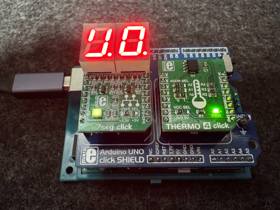
- IMG_0693.jpeg (160.74 KiB) Viewed 2812 times
Do you know how to fix this? I wouldn't alter the original component, but maybe add code to change the LUT.
Andreas
Re: Thermometer project using Mikroe 7seg Click (2x 74HC595) and Mikroe Thermo 4 Click (LM75B)
Posted: Sun Jul 12, 2026 7:34 am
by Bijumon
Hi,
Create a data array with the size of 10 (e.g., 7Seg_data[10]).
Initial with the correct byte values to display numbers from 0 to 9 based on your display type.
Then call ShowSegments as follow
Digit - 0
Segments - 7Seg_data[Digit_Tens]
Digit - 1
Segments - 7Seg_data[Digit_Units]
Re: Thermometer project using Mikroe 7seg Click (2x 74HC595) and Mikroe Thermo 4 Click (LM75B)
Posted: Sun Jul 12, 2026 11:07 am
by andeug
Thank you, now it works as expected!

I am posting the code for my little project, enclosed, so that everyone can see it.
Is it okay for the LM75B I2C's address to be hardcoded, or should this component be changed to allow a custom address? Luckily, in my case, I had a jumper/0R resistor which I could change, but in fixed/final designs it's hard to make changes...
Re: Thermometer project using Mikroe 7seg Click (2x 74HC595) and Mikroe Thermo 4 Click (LM75B)
Posted: Sun Jul 12, 2026 6:05 pm
by Bijumon
Hi,
You can use the I2C Master component to read the temperature from the LM75B, which allows you to use all 8 available addresses on the chip.
This also means you can connect multiple LM75B sensors to the exact same I2C bus, as long as you give each one a different address setting.
Additionally, you can use the SPI Master component to send the display data to the 74HC595 shift registers.
The attached example uses both the I2C Master and SPI Master components.
In this file, the software is configured to use address 0x90 for writing and 0x91 for reading, which matches your default hardware configuration.
where A0, A1, and A2 are all connected to GND.
Best regards,
Re: Thermometer project using Mikroe 7seg Click (2x 74HC595) and Mikroe Thermo 4 Click (LM75B)
Posted: Sun Jul 12, 2026 9:35 pm
by medelec35
Hi.
I have made an unofficial LM75B component update to make it a lot easier for you.
Just create a new folder on your PC and place the attached component in the updated component in it.
Select
File >
Global Settings... >
Locations tab
Within
Look for components in window, add the path of the new folder that contains modified component.
Click
OK, Then
File >
Reload
Now you should be able to select any of the addresses depending on the logic level of pins A0 to A2:
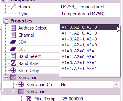
- LM75B Address selection.png (32.36 KiB) Viewed 2667 times