Page 8 of 10
Re: RTC for Miac(Part One)
Posted: Mon Oct 22, 2012 7:55 pm
by Enamul
If your PIC KIT3 is working we can move on with that..
Re: RTC for Miac(Part One)
Posted: Mon Oct 22, 2012 8:02 pm
by JohnCrow
Hi Stuart
Just check your jumpers
J29 below reset button = PSU
J20 to right of J29 = USB
J6 between Port D & D sockets = Default
J5 To left of LCD display = I/O
You could try pulling the jumpers off and on a couple of times make sure they are making good contact.
Also make sure the PPP firmware chip is seated in its socket.
Ensure the board is powered off and the usb cable disconnected - Just in case
Dont think amy of the other jumpers will effect the programming side of things.
Re: RTC for Miac(Part One)
Posted: Mon Oct 22, 2012 8:22 pm
by acestu
OK Enamul just programmed the chip, I am going to put it togethor on a breadboard now, back soon
thanks
Acestu
Re: RTC for Miac(Part One)
Posted: Mon Oct 22, 2012 8:31 pm
by acestu
Hi Enamul,
Do you have a schematic for this circuit please ?
thanks
Acestu
Re: RTC for Miac(Part One)
Posted: Mon Oct 22, 2012 9:59 pm
by Enamul
Hi,
I am not sure which schematic you are looking for..Page 4 has CAN bus schematic which we are using and RTC schematic is in page 1.. SCK is RC3 and SDA is RC4.
so just put RTC module in slave of CAN test board..SCK and SDA
Re: RTC for Miac(Part One)
Posted: Mon Oct 22, 2012 10:10 pm
by acestu
Sorry Enamul, I have got really confused with all this chip swapping, I need the circuit for the chip that I have just programmed with the pickit 3 as I am putting it together on a breadboard and the fcf file only shows an LCD...
thanks
Acestu
Re: RTC for Miac(Part One)
Posted: Mon Oct 22, 2012 10:13 pm
by Enamul
This circuit..but LCD in PORTD for both master and slave..not in PORTC
Re: RTC for Miac(Part One)
Posted: Mon Oct 22, 2012 10:22 pm
by acestu
Thanks,
In the diagram Enamul, 1x unit is called DISPLAY and the other is called COLLECTETOR, what does collector mean ?
Is the display a slave, and the collector a Master ?
Also am I right in thinking that the Master will eventually be the miac unit and the slave has the set date time program on it ?
thanks
Acestu
Re: RTC for Miac(Part One)
Posted: Mon Oct 22, 2012 11:44 pm
by Enamul
In the diagram Enamul, 1x unit is called DISPLAY and the other is called COLLECTETOR, what does collector mean ?
Is the display a slave, and the collector a Master ?
Display is slave..Collector is Master..RTC time & Date collector.
Also am I right in thinking that the Master will eventually be the miac unit and the slave has the set date time program on it ?
Yes..you are right.
Re: RTC for Miac(Part One)
Posted: Tue Oct 23, 2012 6:24 pm
by acestu
Right Enamul,
Am I right in thinking that I am now making the circuit that I made a schematic for on page 4, with the 18f4580 that I have just programmed with the RTC_PIC18f4580_NO_SET code ?
thanks
Acestu
Re: RTC for Miac(Part One)
Posted: Tue Oct 23, 2012 7:07 pm
by Enamul
If your CAN transmission which you have tested earlier is OK we can go to slave_RTC and Master communication..In that case you can simply test slave using the program you mentioned..if clock is running..let me know.
I will post program for Master and modified slave with CAN.
Re: RTC for Miac(Part One)
Posted: Tue Oct 23, 2012 7:26 pm
by acestu
Hi Enamul,
I am sending a picture of the rtc board, I have just plugged it in and the time and date are correct
Thanks
Acestu
Re: RTC for Miac(Part One)
Posted: Tue Oct 23, 2012 8:02 pm
by Enamul
Ok..nice to see that..I think understand that this board will now have CAN IC MCP2551 as well in RB2 and RB3 to connect with Master..I will post shortly the program to transfer this data to Master.
Re: RTC for Miac(Part One)
Posted: Tue Oct 23, 2012 8:09 pm
by acestu
P.S. Don't forget Enamul that the chip in the picture above is a Pic18f458 and NOT Pic18f4580
Thanks
Acestu
Re: RTC for Miac(Part One)
Posted: Tue Oct 23, 2012 10:55 pm
by Enamul
Please put PIC18f4580 in the circuit shown in Picture..with the program RTC_PIC18f4580_NO_SET
Re: RTC for Miac(Part One)
Posted: Tue Oct 23, 2012 11:36 pm
by Enamul
Here is the code for slave and Master where Slave will run RTC and send the data to Master via CAN and Master will receive that data and display.
Re: RTC for Miac(Part One)
Posted: Thu Nov 01, 2012 9:52 pm
by acestu
Hi Enamul,
I have just got my new chips Pic18f4580, I? have loaded the program RTC_PIC184580_NO_SET and I have just put it in the Dev board and clicked on Build/Compile To Chip, now after a few dots appear on the screen the chip configuration window opens but the settings do not look right, ie Watchdog Timer is enabled etc, and I am not sure what all the settings should be, is this right ?

- config_screen.jpg (223.06 KiB) Viewed 16004 times
thanks
Acestu
Re: RTC for Miac(Part One)
Posted: Thu Nov 01, 2012 10:35 pm
by acestu
Ok Enamul , touch wood I think I have sorted it, I now have a programmed chip with the RTC_PIC18F4580_NO_SET code on it.
thanks
Acestu
Re: RTC for Miac(Part One)
Posted: Thu Nov 01, 2012 10:55 pm
by Enamul
Here is the configuration...Be careful PORTB<0:4> as digital not analog.
Re: RTC for Miac(Part One)
Posted: Sat Nov 03, 2012 9:10 pm
by acestu
Hi Enamul,
Back on track now I think after all the trouble I have had with duff chips etc.
Anyway I now have two 20 x 4 LCD modules and I am posting a diagram of the circuit which is what I am going to build next.
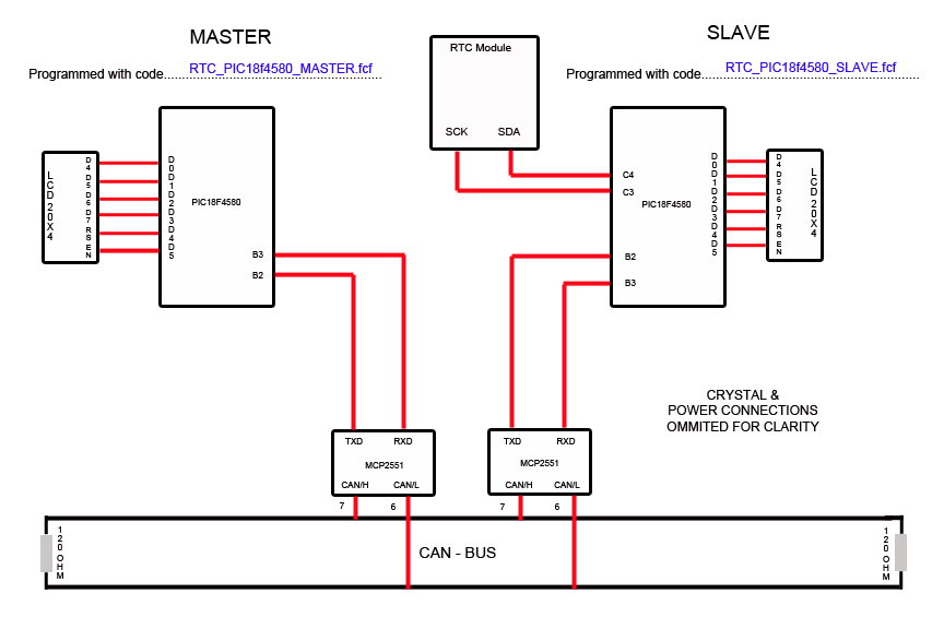
- RTC.jpg (103.22 KiB) Viewed 15923 times
Thanks
Acestu
Re: RTC for Miac(Part One)
Posted: Sat Nov 03, 2012 9:20 pm
by Enamul
Hi Stuart,
Exactly this what I want from you to make in the circuit and put appropriate program. You should see clock running in both display. Later on we will replace Master by MIAC. You are close now. We can open another thread(part two) when this part will finish.
MIAC testing we will do in new thread.
Re: RTC for Miac(Part One)
Posted: Mon Nov 05, 2012 8:19 pm
by acestu
Hi Enamul,
I have set up the circuit as per diagram but I don't get the date on any of the lcd displays, it just shows what is in the pic I have posted.
thanks
Acestu
Do the unused pins on the MCP2551 need to be earthed ?
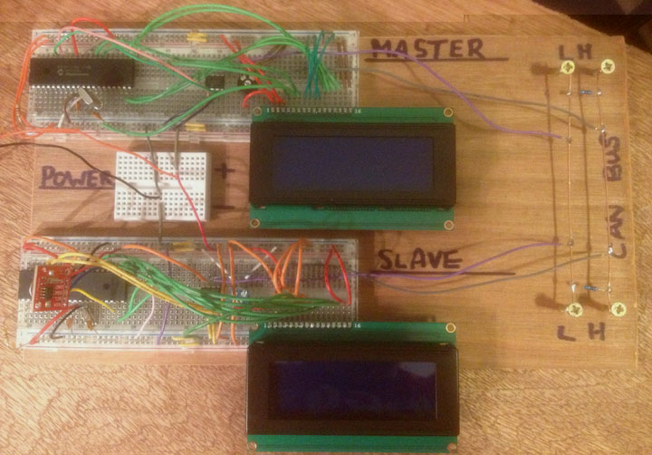
- Final_Setup1.jpg (84.54 KiB) Viewed 15895 times
Re: RTC for Miac(Part One)
Posted: Mon Nov 05, 2012 9:30 pm
by acestu
Ok sorry,
I have had to reprogram the chips they had the old code in them,
Now the Master LCD says "Master RTC Unit" but the Slave LCD says nothing
P.S. Do I have to set the first time before i program the chip in order to get something on the LCD screen ?
thanks
Acestu
Re: RTC for Miac(Part One)
Posted: Mon Nov 05, 2012 10:10 pm
by acestu
Hi Enamul,
I have a spare pic18f4580 chip so I have programmed it with the slave code and set it up on a breadboard but this too does not show anything on the LCD unit
Do you have any ideas please
thanks
Acestu
Re: RTC for Miac(Part One)
Posted: Mon Nov 05, 2012 10:36 pm
by Enamul
Do the unused pins on the MCP2551 need to be earthed ?
No you don't need to do that..
What I can only think you have loaded wrong program..
please just try the following two..put those in a folder with today's date so that you can mark them easily..