Page 4 of 10
Re: RTC for Miac
Posted: Sun Sep 30, 2012 12:24 am
by Enamul
Ok..fine. Here I am attaching two programs for CAN trans-reception..if you can have a look in the attached programs by the time you get the chips. It will be easy to test. The core idea is to test bidirectional CAN transmission here..Master send data to slave and returned back the same to master..so we can confirm both are working.
You can go through the help file of CAN component..
Re: RTC for Miac
Posted: Sun Sep 30, 2012 8:29 pm
by Enamul
Hi Stuart,
Please read also the following post..where lots of information regarding use of internal CAN is mentioned. I have started from this page before using internal CAN.
http://www.matrixmultimedia.com/mmforum ... bus#p19222
Re: RTC for Miac
Posted: Sun Sep 30, 2012 10:01 pm
by acestu
Thanks Enamul,
I| will have a read of that and give you a shout when the parts come....
thanks
Acestu
Re: RTC for Miac(Part One)
Posted: Sun Oct 07, 2012 5:35 pm
by acestu
Hi Enamul,
I had a bit of a problem with the chip order but they are here now....
thanks
Acestu
Re: RTC for Miac(Part One)
Posted: Sun Oct 07, 2012 10:29 pm
by Enamul
Hi Stuart,
Good...you got your ICs..We can now start to test CAN bus. Do you have two LCD or one LCD? If yes, we can easily test bi-directional communication between two chips. If not, we can still test bi-directional communication but we have to connect LCD with Master first and see the result and if everything according to expectation we can swap LCD to slave module and see the result. After that we can move to RTC and CAN based communication of time and date data to Master module. If that works fine then we will finalize code for Miac (Master) and slave RTC communication in that stage you need to order a Miac module.
Hope our plan is clear

Re: RTC for Miac(Part One)
Posted: Sun Oct 07, 2012 10:33 pm
by acestu
Hi Enamul,
Yes I have 2 or 3 lcd modules here, so that is ok
thanks
Acestu
Re: RTC for Miac(Part One)
Posted: Sun Oct 07, 2012 10:34 pm
by Enamul
Great! Did you test the program I have up-loaded or you need a bit of explanation about connection and program?
Re: RTC for Miac(Part One)
Posted: Mon Oct 08, 2012 12:29 am
by acestu
Hi Enamul,
Sorry it has been a while, which program am I looking at now ?
thanks
Acestu
Re: RTC for Miac(Part One)
Posted: Mon Oct 08, 2012 8:29 am
by Enamul
The above two programs...
CAN_BD_Receive_SEND_Slave.fcf
CAN_BD_SEND_Receive_MASTER.fcf
Re: RTC for Miac(Part One)
Posted: Mon Oct 08, 2012 5:29 pm
by acestu
Hi Enamul,
Yes I have looked at the 2 x programs but I am not sure what the little square can represents as it is connected to port C6, is this the little Can tranceiver chip only I am not sure how to hardwire it...
thanks
Acestu
Re: RTC for Miac(Part One)
Posted: Mon Oct 08, 2012 6:04 pm
by Enamul
Hi Stuart,
You have to connect the MCP2551 IC for both the PIC..according to the attached schematic. Then you have to connect terminal 1 of CAN bus with terminal 1 and terminal 2 with 2.
Re: RTC for Miac(Part One)
Posted: Mon Oct 08, 2012 6:27 pm
by acestu
Sorry Enamul,
What I meant was: In the Flowcode programs that you uploaded the little graphic can bus says that "Chip Select is connected to port C6 " but on your schematic C6 is not connected to anything.
thanks
Acestu
Re: RTC for Miac(Part One)
Posted: Mon Oct 08, 2012 7:24 pm
by acestu
Hi Enamul,
This is a diagram I did of the RTC Module Interface that I did once I got things working, it might be helpful for others...
thanks
Acestu
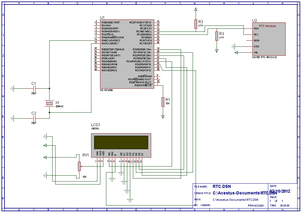
- rtc_pic.jpg (112.57 KiB) Viewed 15788 times
Re: RTC for Miac(Part One)
Posted: Mon Oct 08, 2012 8:26 pm
by Enamul
Yes, it will be helpful to others.
What I meant was: In the Flowcode programs that you uploaded the little graphic can bus says that "Chip Select is connected to port C6 " but on your schematic C6 is not connected to anything.
We are going to use internal CAN of PIC18f4580 which don't use chip select. This is for external CAN and so we are simply ignoring that. We need two connection RB2 and RB3 for CAN connection and those are fixed for this chip.
Here is a the schematic I have from forum...
Re: RTC for Miac(Part One)
Posted: Mon Oct 08, 2012 9:04 pm
by acestu
Hi Enamul,
I have just ordered some breadboards, some 1N4148 diodes and an lm35dz sensor so that I can build all of this, I have the rest of the components, hopefully these should not take long to come... can I just ask though you said we were using 2 x lcd modules so does the collector have an lcd on the same port C ? , and which flowcode program is for which node ?
thanks
Acestu
Re: RTC for Miac(Part One)
Posted: Mon Oct 08, 2012 10:21 pm
by Enamul
Sorry Stuart..I have posted the picture with schematic to give you an idea..but you don't need LM35Dz for the RTC project..But it's a nice temperature sensor which might be useful in other project. You can simply put wiper (center of pot) in ADC pin to get a variable ADC value. If you don't have 1N4148, no problem for testing..you can use that in final product.
LCD in the diagram shown in PORTC but I have told I guess earlier to connect it in PORTD for both node..Because you can't use PORTC for LCD later on as PORTC will be used for RTC module. So, this schematic is not according to program I have posted but to give you an idea of your CAN connection..
Collector node is Master and Display node is slave. you can connect LCD for both and connect POT in Master and can see the change of ADC value in slave.
Re: RTC for Miac(Part One)
Posted: Mon Oct 08, 2012 11:46 pm
by acestu
Not a problem Enamul, I can always use the extra parts but it is the breadboards that I need really because I only have the one that you have seen in the pic and it has the RTC module on it...
thanks
Acestu
Re: RTC for Miac(Part One)
Posted: Thu Oct 11, 2012 7:27 pm
by acestu
Hi Enamul,
I now have the breadboards etc, you said that we could use 2 x LCD modules, do I connect the second LCD to the same ports ?
thanks
Acestu
Re: RTC for Miac(Part One)
Posted: Thu Oct 11, 2012 7:32 pm
by Enamul
Thanks for letting me know. In the posted codes, LCD in both the case are connected to PORTD..your LCD is 16*2 or 20*4?
In the program LCD is 20*4, please change that to 16*2 if that in your case.
Edit: In that case I have to change in code also..please let me know.
Re: RTC for Miac(Part One)
Posted: Thu Oct 11, 2012 7:36 pm
by acestu
Hi Enamul,
Yes my LCD modules are 16 x 2 so I will change it in the flowcode program, I will have a go at putting them together now.
thanks
Acestu
Re: RTC for Miac(Part One)
Posted: Thu Oct 11, 2012 7:44 pm
by acestu
Hi Enamul,
Could you tell me what size the crystals are please , I can't read the schematic it's a bit small...
thank you
Acestu
Re: RTC for Miac(Part One)
Posted: Thu Oct 11, 2012 7:53 pm
by Enamul
Hi,
I have changed the code for 2*16 LCD...20MHz crystal
Re: RTC for Miac(Part One)
Posted: Thu Oct 11, 2012 9:02 pm
by acestu
Hi Enamul,
I am a bit confused, on your schematic you have the crystal on pins 9 and 10, but my datasheet for the 18f4580 says that the osc1 and osc2 pins are 13 and 14
thanks
Acestu
Re: RTC for Miac(Part One)
Posted: Thu Oct 11, 2012 9:43 pm
by Enamul
Sorry all these because of editing...my schematic that I post just above the one you are following. you can see xtal should be in 13 & 14..
Re: RTC for Miac(Part One)
Posted: Thu Oct 11, 2012 9:50 pm
by acestu
Thanks Enamul,
I have just tried to program the chip on my new dev board but it would not program and gave me the enclosed error messages
thanks
Acestu