Page 1 of 1
Problem with EB063
Posted: Tue Aug 02, 2011 7:03 pm
by AndreasR
Hi there,
i am completley unable to comunicate with the E-Blocks EB063 and i need help from the forum.
Following situation:
Multi programmer EB006, 4 pieces of EB063 868MHz.
I wrote a quite simple program with the latest Flowcode for pic (Flowcode v4.5.18.74).
Pic is a 16F877A.
The program should only initialize the EB063, launch to the RF and print received bytes strings or other to a EB005 LC-display.
First problem is that the component macro INIT_RF_MODULE should return a 1 if init is succesfull but everytime a 0 returns.
All the rest of the small program does not show any received RF Code.
I tried all 4 Modules.
I think the E-Block will not be initialized and so it does not work.
Please

give me an advise where the problem is.
Please look at the attachment. The code says more than thousand words.
Re: Problem with EB063
Posted: Wed Aug 03, 2011 10:13 am
by Sean
Hello,
I have checked your program. The connections selected for the RF component do not match either of the default jumper options. Can you confirm that the EB063 jumper is in the 'PATCH' location and that all the signal connections have been correctly made using wire links.
In receive mode, the rf transceiver will only receive signals from a compatible source - requiring matching centre frequency, Baud rate and sync pattern.
Is the transmitter also an e-blocks based system?
Re: Problem with EB063
Posted: Wed Aug 03, 2011 10:48 am
by AndreasR
Sean wrote:Hello,
I have checked your program. The connections selected for the RF component do not match either of the default jumper options. Can you confirm that the EB063 jumper is in the 'PATCH' location and that all the signal connections have been correctly made using wire links.
In receive mode, the rf transceiver will only receive signals from a compatible source - requiring matching centre frequency, Baud rate and sync pattern.
Is the transmitter also an e-blocks based system?
Hello Sean,
thank you for your fast answer.
I´m not sure what do you mean.
The Data Sheet says to take Jumper Block B for a 16F877A. All Jumpers on Block B were set when i receive the E-Blocks.
Is this not correct?
What have i to do in the connections settings when i install the E-Block to Port D of the Multiprogrammer and when i take the "Default Jumper settings"?
You are right, the transmitter is not another E-Block.
The transmitter is a homeautomation switch (4-keys) from ELV Germany sending at 868MHZ.
I will try to read the sended information.
The intention is to show which key is pressed.
Is this possible?
Andreas
Re: Problem with EB063
Posted: Wed Aug 03, 2011 11:31 am
by Sean
Hello Andreas,
The connection jumper links on the E-blocks are used to provide default connections that are useful for most devices. In the case of the EB-063 the connections selected with the jumper in the B position are based on the hardware SPI connections of the PIC16F877A on Port C (used if Hardware SPI is selected in the RF component properties).
As your program uses Software SPI, any port and pins can be selected for the connections, however, these must still be configured correctly on the E-block.
On the EB063, the B jumper links make the following physical connections:
Edited - see below
FSEL = pin 1
CS = pin 0
SDO = pin 5
SDI = pin 4
SCK = pin 3
To use the connections currently selected in the program, the jumper would need to be in the 'Patch' position, with the connections made using single core wire links between J8 and J9.
In data mode the transceiver uses a shift register to receive bytes of data. Data will only be received if the sync pattern (configured in the RF component properties) is received first. This is used to help prevent noise from being received as unwanted data.
A busts of alternating 1s and 0s (pre-amble) is also helpful to synchronize transmit and receive timers. The modules on the EB063 transmit the pre-amble and sync pattern before sening data when in transmit mode. The devices you are trying to detect would need to transmit data using the same protocol.
The EB063 can also be used in FSEL mode (see the component properties). This bypasses all buffering and puts received signals directly onto the FSEL pin of the E-block. It might be possible to detect devices that are not compatible with the EB063 data mode by reading this pin (using the component FSK_Read macro).
Re: Problem with EB063
Posted: Wed Aug 03, 2011 12:33 pm
by AndreasR
Dear Sean,
thank you very much to open my eyes.

I was so stupid that i forgot to control the pin numbers listed in the documentation and set them in the properties dialogue of the EB063.
After correction of the pin assignments most things work fine.
Next step ist to test FSEL, because transmission of the switches ist fixed.
I will tell you and the rest of the forum if it is possible to launch the communication of the switch.
Andreas
Re: Problem with EB063
Posted: Wed Aug 03, 2011 9:38 pm
by JohnCrow
Sean wrote:
On the EB063, the B jumper links make the following physical connections:
FSEL = pin 1
CS = pin 0
SDO = pin 3
SDI = pin 4
SCK = pin 5
Hi Sean
I dont want to confuse anyone, but Ive just looked at the data sheet for the RF e-block and it shows the connection with jumber B as
FSEL = pin 1
CS = pin 0
SDO = pin 5
SDI = pin 4
SCK = pin 3
ie the sdo and sck are the opposite way round to your last post.
The datasheet pins also seam to tie up with the pin out on the 16F877A
Pin 18 RC3 / SCK
Pin 24 RC5 / SDO
Re: Problem with EB063
Posted: Thu Aug 04, 2011 9:59 am
by Sean
Thanks John.
I have edited the original post to try to avoid any confusion.
Re: Problem with EB063
Posted: Tue Aug 16, 2011 5:10 pm
by JohnCrow
Hi
I am having the same problem as AndreasR,
I cannot get the RF eblock to work
I tried this simple program to just check if the board is initalising and it isn't
Must be something not quite right. Any suggestions please?
Re: Problem with EB063
Posted: Wed Aug 17, 2011 10:55 am
by Sean
Hello,
The RF component help file information appears to be out of date.
As there was no definitive way to detect successful initialization of the RF module, the initialization macro now returns an integer value containing the module's status register contents.
The returned value is dependent on the electrical and rf conditions at the time of initialization
Bits 15-11 contain latched interrupt/event flags.
Bits 8-0 are used to indicate the presence and quality of any detected signal.
The states of both of these collections of bits will vary depending on conditions.
Bits 9 and 10 should contain more reliable values and can be masked out from the return value.
Bit 9 (mask value = 512) will be set ('1') if the receive buffer is empty - as it should be immediately after initialization.
Bit 10 (mask value = 1024) will be clear ('0') if the supply voltage is within the normal operating range.
The help file information will be updated as soon as possible.
If information is required urgently, details of the RF module controller can be found in the MRF49XA data sheet available from Microchip.
Re: Problem with EB063
Posted: Thu Aug 18, 2011 11:10 am
by AndreasR
Very frustrating the EB063

I try a very small and stupid basic function with the macros RF_Send_Byte and RF_Receive_Byte for some days. Nothing happens, nothing works and i have no idea.
Please give me a hint.
The facts:
Sender is PIC 16F88 with crystal resonator of 6MHz, and an EB063. All built on a small vero pinboard.
Every xxx milliseconds he should send a Byte.
It seems to work correct.
Receiver is built on EB006 Board with PIC 16F877 and aother EB063.
In an endless loop a Byte should be received via RF_Receive and be shown on LCD.
But nothing happens.
Andreas
Re: Problem with EB063
Posted: Thu Aug 18, 2011 12:35 pm
by Sean
Hello Andreas,
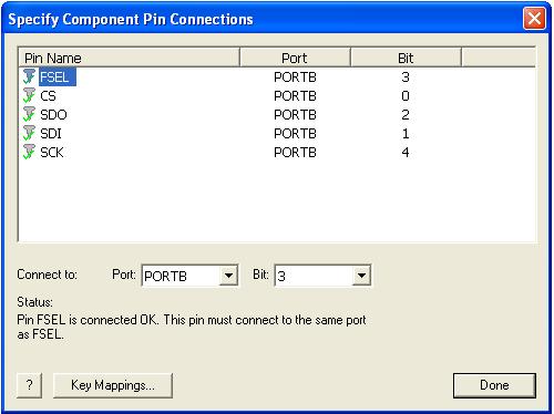
I have checked both of your programs, and there still seems to be a problem with the connections. The correct pins are being used for Jumper A with the 16F88, and Jumper B with the 16F877A. But in both cases the SDI and SDO pins have been swapped.
The connections displayed by Flowcode for each jumper option are shown below (the ports can be changed when using Software mode).
Jumper A:
- RF_Jumper_A.JPG (27.37 KiB) Viewed 13144 times
Jumper B:

- RF_Jumper_B.JPG (26.63 KiB) Viewed 13144 times
Re: Problem with EB063
Posted: Thu Aug 18, 2011 4:39 pm
by AndreasR
Hi Sean,
you are right if i only use the Transmitter (16F887).
I made a mistake when inserting the wireless part.
After changing SDi and SDO again nothing happens.
Then i changed the SDI and SDO Ports on the 16F88 and again nothing happens.
At the 16F88 part (1second pulse sender) i do not use the Jumper Blocks A or B because i do not connect the E-Block via Sub-D.
I use the Patch Jumper Field and connect the Block via the Pinout directly.
The connection i made is :
FSEL Port B PIN 3
CS Port B PIN 0
SDO Port B PIN 2
SDI Port B PIN 1
SCK Port B PIN 4
Is there anything wrong in my thought?
Andreas
Re: Problem with EB063
Posted: Thu Aug 18, 2011 5:58 pm
by AndreasR
Hey ho seems it works
After i changed the SDI and SDO pins nothing happens.
Then i fingered out at the pulse generator with 16F88 that you must be extremly careful when not using the Sub-D connectors.
Noise was the problem

The wires between the E-Block and the PIC are about 5cm long.
Sometimes it seems this works like an antenna on the wires between the two parts.
Andreas
Re: Problem with EB063
Posted: Thu Aug 18, 2011 6:08 pm
by AndreasR
By the way,
another question to the magicians from matrix:
What´s about the switch
Hardware SPI at the external properties.
When i switch it on and compile to hex then i get fllowing error:
16F88-Sender-Sekundenpuls-senden-2.c(992): error: missing semicolon
16F88-Sender-Sekundenpuls-senden-2.c failure
failure
Return code = 1
This error i get on all testfiles with any PICs as soon as i switch to hardware SPI.
Is there a declaration of this switch?
I don´t understand the text at the help file.
SPI Communications - Software allows pin connections to be defined via the component connections window.
SPI Communications - Hardware allows the SPI hardware to be used. Only the chip select pin is available for free allocation.
Thanks to matrix for your patience
Andreas