Difference between revisions of "Component: Level (DSP)"
From Flowcode Help
Jump to navigationJump to search| Line 16: | Line 16: | ||
==Detailed description== | ==Detailed description== | ||
| + | |||
| + | |||
| Line 26: | Line 28: | ||
==Examples== | ==Examples== | ||
| + | |||
| + | |||
| Line 73: | Line 77: | ||
|- | |- | ||
|- | |- | ||
| − | | width="10%" align="center" style="border-top: 2px solid #000;" | [[File:]] - | + | | width="10%" align="center" style="border-top: 2px solid #000;" | [[File:Fc9-s32-icon.png]] - LONG |
| width="90%" style="border-top: 2px solid #000;" | ''Return'' | | width="90%" style="border-top: 2px solid #000;" | ''Return'' | ||
|} | |} | ||
| Line 86: | Line 90: | ||
|- | |- | ||
|- | |- | ||
| − | | width="10%" align="center" style="border-top: 2px solid #000;" | [[File:]] - | + | | width="10%" align="center" style="border-top: 2px solid #000;" | [[File:Fc9-s32-icon.png]] - LONG |
| width="90%" style="border-top: 2px solid #000;" | ''Return'' | | width="90%" style="border-top: 2px solid #000;" | ''Return'' | ||
|} | |} | ||
| Line 125: | Line 129: | ||
|- | |- | ||
|- | |- | ||
| − | | width="10%" align="center" style="border-top: 2px solid #000;" | [[File:]] - | + | | width="10%" align="center" style="border-top: 2px solid #000;" | [[File:Fc9-s32-icon.png]] - LONG |
| width="90%" style="border-top: 2px solid #000;" | ''Return'' | | width="90%" style="border-top: 2px solid #000;" | ''Return'' | ||
|} | |} | ||
| Line 164: | Line 168: | ||
|- | |- | ||
| width="10%" align="center" | [[File:Fc9-type-17-icon.png]] | | width="10%" align="center" | [[File:Fc9-type-17-icon.png]] | ||
| + | | width="90%" | Connect To | ||
| + | |- | ||
| + | | colspan="2" | DSP component with output buffer to collect our data from. | ||
| + | |- | ||
| + | | width="10%" align="center" | [[File:Fc9-type-16-icon.png]] | ||
| width="90%" | Connect To | | width="90%" | Connect To | ||
|- | |- | ||
Revision as of 15:27, 17 December 2021
| Author | Matrix Ltd |
| Version | 1.2 |
| Category | DSP |
Contents
Level component
Allows for detection and collection of peaks, troughs and averages.
Detailed description
No detailed description exists yet for this component
Examples
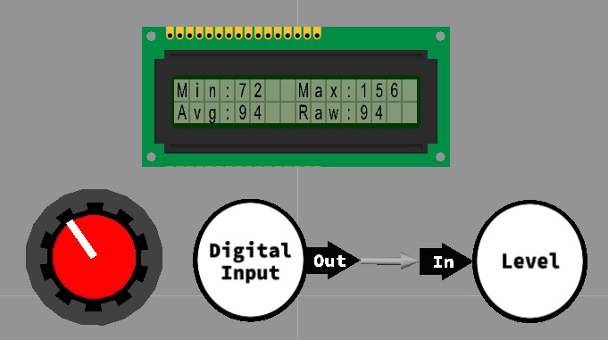
Here is a basic example of the Level component. The example collects the max, min and average readings from the buffer and displays them on the LCD display.
The values in the buffer are defined using the InputADC component.
Min: Minimum (smallest) value read from the buffer.
Max: Maximum (largest) value read from the buffer.
Average: Rolling average calculated from the values inside the buffer.
Downloadable macro reference
| ReadTroughArray | |
| Returns the lowest value from the last "Decay" number of buffers. | |
| Return | |
| ReadTrough | |
| Returns the lowest value from the last "Decay" number of index locations. | |
| Return | |
| ReadAverage | |
| Returns the average from the last "Decay" number of index locations. | |
| Return | |
| ReadPeakArray | |
| Returns the highest value from the last "Decay" number of buffers. | |
| Return | |
| ReadAverageArray | |
| Returns the average from the last "Decay" number of buffers. | |
| Return | |
| ReadPeak | |
| Returns the highest value from the last "Decay" number of index locations. | |
| Return | |
| ResetRecords | |
| Allows the peak and trough to be reset back to default values. | |
| ResetPeak | |
| ResetTrough | |
| Return | |
