Difference between revisions of "Component: Target Chip (Advanced Shapes)"
From Flowcode Help
Jump to navigationJump to search (XML import - Pre 8.0 release) |
|||
| (5 intermediate revisions by the same user not shown) | |||
| Line 1: | Line 1: | ||
| − | + | {| style="width:50%" | |
| − | |||
| − | {| | ||
|- | |- | ||
| − | | width="20%" style="color: gray;" | Author | + | | width="20%" style="color:gray;" | Author |
| Matrix Ltd | | Matrix Ltd | ||
|- | |- | ||
| − | | width="20%" style="color: gray;" | Version | + | | width="20%" style="color:gray;" | Version |
| − | | 1.0 | + | | 1.0 |
|- | |- | ||
| − | | width="20%" style="color: gray;" | Category | + | | width="20%" style="color:gray;" | Category |
| Advanced Shapes | | Advanced Shapes | ||
|} | |} | ||
| + | |||
| + | |||
| + | ==Target Chip component== | ||
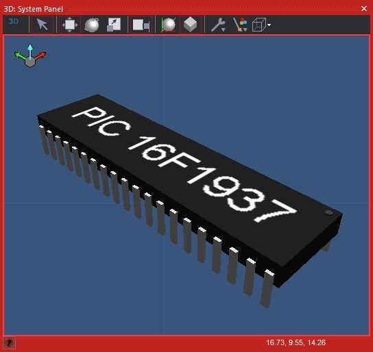
| + | A cosmetic only representation of the target microcontoller device showing the default package type complete with pins. | ||
| + | |||
| + | ==Component Pack== | ||
| + | |||
| + | FREE | ||
| + | |||
| + | ==Detailed description== | ||
| + | |||
| + | |||
| + | |||
| + | |||
| + | |||
| − | |||
| − | |||
| − | |||
| − | |||
| − | + | ''No detailed description exists yet for this component'' | |
| − | + | ==Examples== | |
| − | |||
| − | |||
| − | |||
| − | |||
| − | |||
| − | |||
| − | |||
| − | |||
| − | |||
| − | |||
| − | |||
| − | + | A really simple component that creates a chip on the Flowcode panel representing your target microcontroller. | |
| − | + | Useful if your designing a component with a PCB and want the panel graphics to replicate the real world electronics. | |
| − | + | [[File:TargetChip.jpg]] | |
| − | + | ==Downloadable macro reference== | |
| − | |||
| − | |||
| − | + | ==Property reference== | |
| − | Number of pins on the current selected target micrcontroller family in your project. | + | {| class="wikitable" style="width:60%; background-color:#FFFFFF;" |
| + | |- | ||
| + | | width="10%" align="center" style="background-color:#D8C9D8;" | [[File:Fc9-prop-icon.png]] | ||
| + | | width="90%" style="background-color:#D8C9D8; color:#4B008D;" | '''Properties''' | ||
| + | |- | ||
| + | |- | ||
| + | | width="10%" align="center" | [[File:Fc9-type-10-icon.png]] | ||
| + | | width="90%" | Device Name | ||
| + | |- | ||
| + | | colspan="2" | Name of the current selected target micrcontroller in your project. | ||
| + | |- | ||
| + | | width="10%" align="center" | [[File:Fc9-type-10-icon.png]] | ||
| + | | width="90%" | Device Family | ||
| + | |- | ||
| + | | colspan="2" | Name of the current selected target micrcontroller family in your project. | ||
| + | |- | ||
| + | | width="10%" align="center" | [[File:Fc9-type-21-icon.png]] | ||
| + | | width="90%" | Number Sides | ||
| + | |- | ||
| + | | colspan="2" | Minimum number of sides on the current selected target micrcontroller in your project. 2 sides usually indicates rectangular DIL / SOIC / SSOP packages. 4 sides usually indicates square TQFP / QFN packages. | ||
| + | |- | ||
| + | | width="10%" align="center" | [[File:Fc9-type-21-icon.png]] | ||
| + | | width="90%" | Number Pins | ||
| + | |- | ||
| + | | colspan="2" | Number of pins on the current selected target micrcontroller family in your project. | ||
| + | |} | ||
Latest revision as of 17:19, 9 November 2022
| Author | Matrix Ltd |
| Version | 1.0 |
| Category | Advanced Shapes |
Contents
Target Chip component
A cosmetic only representation of the target microcontoller device showing the default package type complete with pins.
Component Pack
FREE
Detailed description
No detailed description exists yet for this component
Examples
A really simple component that creates a chip on the Flowcode panel representing your target microcontroller.
Useful if your designing a component with a PCB and want the panel graphics to replicate the real world electronics.
