Difference between revisions of "Component: Servo Motor Controller (Mechatronics)"
(Created page with "{| style="width:50%" |- | width="20%" style="color:gray;" | Author | Matrix Ltd |- | width="20%" style="color:gray;" | Version | 2.0 |- | width="20%" style="color:gray...") |
|||
| (4 intermediate revisions by the same user not shown) | |||
| Line 5: | Line 5: | ||
|- | |- | ||
| width="20%" style="color:gray;" | Version | | width="20%" style="color:gray;" | Version | ||
| − | | 2. | + | | 2.1 |
|- | |- | ||
| width="20%" style="color:gray;" | Category | | width="20%" style="color:gray;" | Category | ||
| Line 14: | Line 14: | ||
==Servo Motor Controller component== | ==Servo Motor Controller component== | ||
Can control up to eight standard PWM driven servo's. Supports 8-bit and 16-bit movement resolutions. 'Servo Object' properties allow you to connect the controller to on-screen simulations using the "Servo Motor" component and its derivatives. | Can control up to eight standard PWM driven servo's. Supports 8-bit and 16-bit movement resolutions. 'Servo Object' properties allow you to connect the controller to on-screen simulations using the "Servo Motor" component and its derivatives. | ||
| + | |||
| + | ==Component Pack== | ||
| + | |||
| + | MECHATRONICS | ||
==Detailed description== | ==Detailed description== | ||
| + | |||
| + | |||
| + | |||
| + | |||
| + | |||
| + | |||
| + | |||
| + | |||
| + | |||
| + | |||
''No detailed description exists yet for this component'' | ''No detailed description exists yet for this component'' | ||
==Examples== | ==Examples== | ||
| + | |||
| + | |||
| + | |||
| + | |||
| + | |||
| + | |||
| + | |||
| + | |||
| + | |||
| + | |||
| Line 321: | Line 345: | ||
|} | |} | ||
| + | |||
| + | |||
| + | |||
| + | ==Property reference== | ||
{| class="wikitable" style="width:60%; background-color:#FFFFFF;" | {| class="wikitable" style="width:60%; background-color:#FFFFFF;" | ||
|- | |- | ||
| − | | width="10%" align="center" style="background-color:#D8C9D8; | + | | width="10%" align="center" style="background-color:#D8C9D8;" | [[File:Fc9-prop-icon.png]] |
| − | | width="90%" style="background-color:#D8C9D8; color:#4B008D;" | ''' | + | | width="90%" style="background-color:#D8C9D8; color:#4B008D;" | '''Properties''' |
| + | |- | ||
| + | |- | ||
| + | | width="10%" align="center" | [[File:Fc9-type-16-icon.png]] | ||
| + | | width="90%" | Channels (1 - 8) | ||
| + | |- | ||
| + | | colspan="2" | Set the number of servo's that you need to control. Value from 1 to 8. | ||
| + | |- | ||
| + | | width="10%" align="center" style="background-color:#EAE1EA;" | [[File:Fc9-conn-icon.png]] | ||
| + | | width="90%" style="background-color:#EAE1EA; color:#4B008D;" | Connections | ||
| + | |- | ||
| + | |- | ||
| + | | width="10%" align="center" | [[File:Fc9-type-5-icon.png]] | ||
| + | | width="90%" | Channel 0 | ||
| + | |- | ||
| + | | colspan="2" | Pin on which to output PWM for the servo motor. | ||
| + | |- | ||
| + | | width="10%" align="center" | [[File:Fc9-type-5-icon.png]] | ||
| + | | width="90%" | Channel 1 | ||
| + | |- | ||
| + | | colspan="2" | Pin on which to output PWM for the servo motor. | ||
|- | |- | ||
| − | | | + | | width="10%" align="center" | [[File:Fc9-type-5-icon.png]] |
| + | | width="90%" | Channel 2 | ||
|- | |- | ||
| + | | colspan="2" | Pin on which to output PWM for the servo motor. | ||
|- | |- | ||
| − | | width="10%" align="center" | [[File:Fc9- | + | | width="10%" align="center" | [[File:Fc9-type-5-icon.png]] |
| − | | width="90%" | | + | | width="90%" | Channel 3 |
|- | |- | ||
| − | | colspan="2" | | + | | colspan="2" | Pin on which to output PWM for the servo motor. |
|- | |- | ||
| − | | width="10%" align="center | + | | width="10%" align="center" | [[File:Fc9-type-5-icon.png]] |
| − | | width="90% | + | | width="90%" | Channel 4 |
| − | |||
| − | |||
| − | |||
| − | |||
|- | |- | ||
| − | | | + | | colspan="2" | Pin on which to output PWM for the servo motor. |
| − | |||
|- | |- | ||
| − | | | + | | width="10%" align="center" | [[File:Fc9-type-5-icon.png]] |
| + | | width="90%" | Channel 5 | ||
|- | |- | ||
| + | | colspan="2" | Pin on which to output PWM for the servo motor. | ||
|- | |- | ||
| − | | width="10%" align="center | + | | width="10%" align="center" | [[File:Fc9-type-5-icon.png]] |
| − | | width="90% | + | | width="90%" | Channel 6 |
| − | | | + | |- |
| − | + | | colspan="2" | Pin on which to output PWM for the servo motor. | |
| − | |||
| − | |||
| − | |||
| − | |||
| − | |||
| − | |||
|- | |- | ||
| − | | width="10%" align="center | + | | width="10%" align="center" | [[File:Fc9-type-5-icon.png]] |
| − | | width="90% | + | | width="90%" | Channel 7 |
|- | |- | ||
| + | | colspan="2" | Pin on which to output PWM for the servo motor. | ||
|- | |- | ||
| − | | width="10%" align="center" | [[File:Fc9- | + | | width="10%" align="center" style="background-color:#EAE1EA;" | [[File:Fc9-conn-icon.png]] |
| − | | width="90%" | | + | | width="90%" style="background-color:#EAE1EA; color:#4B008D;" | Resources |
|- | |- | ||
| − | |||
|- | |- | ||
| width="10%" align="center" | [[File:Fc9-type-10-icon.png]] | | width="10%" align="center" | [[File:Fc9-type-10-icon.png]] | ||
| Line 372: | Line 413: | ||
|- | |- | ||
| colspan="2" | Lists the internal peripherals of the MCU used by the component. When the servo motor is initialised you will not be able to use the listed peripherals for other functionality. | | colspan="2" | Lists the internal peripherals of the MCU used by the component. When the servo motor is initialised you will not be able to use the listed peripherals for other functionality. | ||
| + | |- | ||
| + | | width="10%" align="center" style="background-color:#EAE1EA;" | [[File:Fc9-conn-icon.png]] | ||
| + | | width="90%" style="background-color:#EAE1EA; color:#4B008D;" | Trim | ||
| + | |- | ||
|- | |- | ||
| width="10%" align="center" | [[File:Fc9-type-16-icon.png]] | | width="10%" align="center" | [[File:Fc9-type-16-icon.png]] | ||
| Line 417: | Line 462: | ||
|- | |- | ||
| colspan="2" | Trim the pulse width for this channel. Use this to trim the positioning of two servos so that similar input values will produce the same degree of movement. | | colspan="2" | Trim the pulse width for this channel. Use this to trim the positioning of two servos so that similar input values will produce the same degree of movement. | ||
| + | |- | ||
| + | | width="10%" align="center" style="background-color:#EAE1EA;" | [[File:Fc9-conn-icon.png]] | ||
| + | | width="90%" style="background-color:#EAE1EA; color:#4B008D;" | Pulse Width | ||
| + | |- | ||
|- | |- | ||
| width="10%" align="center" | [[File:Fc9-type-21-icon.png]] | | width="10%" align="center" | [[File:Fc9-type-21-icon.png]] | ||
| Line 433: | Line 482: | ||
| colspan="2" | Number of instructions for 1 / 256th of the positional accuracy. This sets the default movement speed to maintain legacy move speeds. Also sets the multiplication factor to convert from a byte 0-255 to a clocked position value. | | colspan="2" | Number of instructions for 1 / 256th of the positional accuracy. This sets the default movement speed to maintain legacy move speeds. Also sets the multiplication factor to convert from a byte 0-255 to a clocked position value. | ||
|- | |- | ||
| − | | width="10%" align="center" style="background-color:# | + | | width="10%" align="center" style="background-color:#EAE1EA;" | [[File:Fc9-conn-icon.png]] |
| − | | width="90%" style="background-color:# | + | | width="90%" style="background-color:#EAE1EA; color:#4B008D;" | Simulation |
| − | |||
| − | |||
| − | |||
| − | |||
| − | |||
| − | |||
| − | |||
| − | |||
| − | |||
| − | |||
| − | |||
| − | |||
| − | |||
| − | |||
| − | |||
| − | |||
| − | |||
| − | |||
| − | |||
| − | |||
| − | |||
| − | |||
| − | |||
| − | |||
| − | |||
| − | |||
| − | |||
| − | |||
| − | |||
| − | |||
| − | |||
| − | |||
| − | |||
| − | |||
| − | |||
| − | |||
| − | |||
| − | |||
| − | |||
| − | |||
| − | |||
| − | |||
| − | |||
| − | |||
|- | |- | ||
|- | |- | ||
Latest revision as of 17:26, 9 November 2022
| Author | Matrix Ltd |
| Version | 2.1 |
| Category | Mechatronics |
Contents
Servo Motor Controller component
Can control up to eight standard PWM driven servo's. Supports 8-bit and 16-bit movement resolutions. 'Servo Object' properties allow you to connect the controller to on-screen simulations using the "Servo Motor" component and its derivatives.
Component Pack
MECHATRONICS
Detailed description
No detailed description exists yet for this component
Examples
Importing from v5
The servo component in Flowcode v6 onwards has a new Initialise macro which will need to be added to your program before any other calls to the servo motor component are made.
Controlling a servo with an analogue input
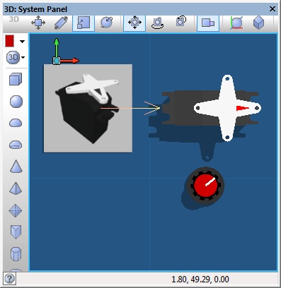
This example reads the value of the analogue potentiometer and uses this to set the position of the servo motor.
![]() Servo Example 1
The Servo controller is linked to the standard servo component but this could be linked to any object on the panel.
Servo Example 1
The Servo controller is linked to the standard servo component but this could be linked to any object on the panel.
Creating a multi-axis actuator using servo motors
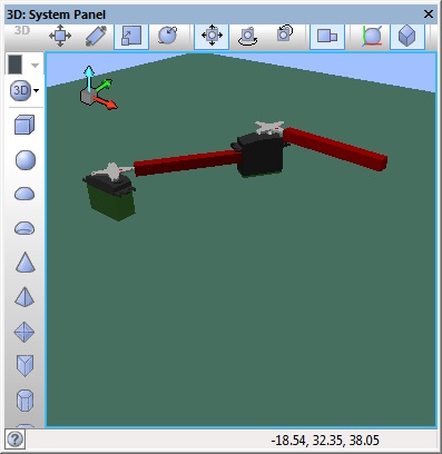
This example links two servo motors together using panel primitive objects and groups.
![]() Servo Example 2
The Servo controller can handle up to 8 motors and is used to control both of the standard servo components on the panel.
Servo Example 2
The Servo controller can handle up to 8 motors and is used to control both of the standard servo components on the panel.
Downloadable macro reference
| DisableServo | |
| Disables a servo channel effectivly disabling the motor. | |
| Channel | |
| The channel to set the position for. First channel is zero. | |
| Return | |
| IsAutoMoving | |
| Is the AutoMoveToPosition movement complete. Returns 1 if the servos are still moving. Returns 0 if all servo movement is complete. | |
| Return | |
| Initialise | |
| Sets up the servo motor interrupts | |
| Return | |

