|
|
| (4 intermediate revisions by the same user not shown) |
| Line 14: |
Line 14: |
| | ==LED (Generic, RGB) component== | | ==LED (Generic, RGB) component== |
| | An LED with red, green and blue elements that can be mixed together to produce almost any colour at any brightness. | | An LED with red, green and blue elements that can be mixed together to produce almost any colour at any brightness. |
| | + | |
| | + | ==Component Pack== |
| | + | |
| | + | BASICIO |
| | | | |
| | ==Detailed description== | | ==Detailed description== |
| | + | |
| | + | |
| | + | |
| | + | |
| | + | |
| | + | |
| | + | |
| | + | |
| | + | |
| | + | |
| | | | |
| | | | |
| Line 22: |
Line 36: |
| | | | |
| | ==Examples== | | ==Examples== |
| | + | |
| | + | |
| | + | |
| | + | |
| | + | |
| | + | |
| | + | |
| | + | |
| | + | |
| | + | |
| | | | |
| | | | |
| Line 135: |
Line 159: |
| | |- | | |- |
| | | colspan="2" | Blue component of RGB LED local to this macro | | | colspan="2" | Blue component of RGB LED local to this macro |
| − | |-
| |
| − | | width="10%" align="center" style="border-top: 2px solid #000;" | [[File:Fc9-void-icon.png]] - VOID
| |
| − | | width="90%" style="border-top: 2px solid #000;" | ''Return''
| |
| − | |}
| |
| − |
| |
| − |
| |
| − | {| class="wikitable" style="width:60%; background-color:#FFFFFF;"
| |
| − | |-
| |
| − | | width="10%" align="center" style="background-color:#D8C9D8;" align="center" | [[File:Fc9-comp-macro.png]]
| |
| − | | width="90%" style="background-color:#D8C9D8; color:#4B008D;" | '''WriteMicroseconds'''
| |
| − | |-
| |
| − | | colspan="2" | Sets the PWM output of one of the PCA9685 pins based on the input microseconds, output is not precise
| |
| − | |-
| |
| − | |-
| |
| − | | width="10%" align="center" | [[File:Fc9-u8-icon.png]] - BYTE
| |
| − | | width="90%" | Output
| |
| − | |-
| |
| − | | colspan="2" | One of the PWM output pins - Range: 0 to 15
| |
| − | |-
| |
| − | | width="10%" align="center" | [[File:Fc9-u16-icon.png]] - UINT
| |
| − | | width="90%" | Microseconds
| |
| − | |-
| |
| − | | colspan="2" | The number of Microseconds to turn the PWM output ON
| |
| − | |-
| |
| − | | width="10%" align="center" style="border-top: 2px solid #000;" | [[File:Fc9-void-icon.png]] - VOID
| |
| − | | width="90%" style="border-top: 2px solid #000;" | ''Return''
| |
| − | |}
| |
| − |
| |
| − |
| |
| − | {| class="wikitable" style="width:60%; background-color:#FFFFFF;"
| |
| − | |-
| |
| − | | width="10%" align="center" style="background-color:#D8C9D8;" align="center" | [[File:Fc9-comp-macro.png]]
| |
| − | | width="90%" style="background-color:#D8C9D8; color:#4B008D;" | '''SetPWM'''
| |
| − | |-
| |
| − | | colspan="2" | Sets the PWM output of one of the PCA9685 pins
| |
| − | |-
| |
| − | |-
| |
| − | | width="10%" align="center" | [[File:Fc9-u8-icon.png]] - BYTE
| |
| − | | width="90%" | Output
| |
| − | |-
| |
| − | | colspan="2" | One of the PWM output pins - Range: 0 to 15
| |
| − | |-
| |
| − | | width="10%" align="center" | [[File:Fc9-u16-icon.png]] - UINT
| |
| − | | width="90%" | On
| |
| − | |-
| |
| − | | colspan="2" | At what point in the 4096-part cycle to turn the PWM output ON
| |
| − | |-
| |
| − | | width="10%" align="center" | [[File:Fc9-u16-icon.png]] - UINT
| |
| − | | width="90%" | Off
| |
| − | |-
| |
| − | | colspan="2" | At what point in the 4096-part cycle to turn the PWM output OFF
| |
| − | |-
| |
| − | | width="10%" align="center" style="border-top: 2px solid #000;" | [[File:Fc9-void-icon.png]] - VOID
| |
| − | | width="90%" style="border-top: 2px solid #000;" | ''Return''
| |
| − | |}
| |
| − |
| |
| − |
| |
| − | {| class="wikitable" style="width:60%; background-color:#FFFFFF;"
| |
| − | |-
| |
| − | | width="10%" align="center" style="background-color:#D8C9D8;" align="center" | [[File:Fc9-comp-macro.png]]
| |
| − | | width="90%" style="background-color:#D8C9D8; color:#4B008D;" | '''Initialise'''
| |
| − | |-
| |
| − | | colspan="2" | Sets up the I2C ready for communications to begin
| |
| − | |-
| |
| − | |-
| |
| − | | width="10%" align="center" style="border-top: 2px solid #000;" | [[File:Fc9-void-icon.png]] - VOID
| |
| − | | width="90%" style="border-top: 2px solid #000;" | ''Return''
| |
| − | |}
| |
| − |
| |
| − |
| |
| − | {| class="wikitable" style="width:60%; background-color:#FFFFFF;"
| |
| − | |-
| |
| − | | width="10%" align="center" style="background-color:#D8C9D8;" align="center" | [[File:Fc9-comp-macro.png]]
| |
| − | | width="90%" style="background-color:#D8C9D8; color:#4B008D;" | '''WakeUp'''
| |
| − | |-
| |
| − | | colspan="2" | Wakes the module from Sleep mode
| |
| − | |-
| |
| − | |-
| |
| − | | width="10%" align="center" style="border-top: 2px solid #000;" | [[File:Fc9-void-icon.png]] - VOID
| |
| − | | width="90%" style="border-top: 2px solid #000;" | ''Return''
| |
| − | |}
| |
| − |
| |
| − |
| |
| − | {| class="wikitable" style="width:60%; background-color:#FFFFFF;"
| |
| − | |-
| |
| − | | width="10%" align="center" style="background-color:#D8C9D8;" align="center" | [[File:Fc9-comp-macro.png]]
| |
| − | | width="90%" style="background-color:#D8C9D8; color:#4B008D;" | '''SetPin'''
| |
| − | |-
| |
| − | | colspan="2" | Sets pin without having to deal with on/off tick placement and properly handles a zero value as completely off and 4095 as completely on.
| |
| − | |-
| |
| − | |-
| |
| − | | width="10%" align="center" | [[File:Fc9-u8-icon.png]] - BYTE
| |
| − | | width="90%" | Output
| |
| − | |-
| |
| − | | colspan="2" | One of the PWM output pins - Range: 0 to 15
| |
| − | |-
| |
| − | | width="10%" align="center" | [[File:Fc9-u16-icon.png]] - UINT
| |
| − | | width="90%" | Duty
| |
| − | |-
| |
| − | | colspan="2" | The number of ticks out of 4096 to be active
| |
| − | |-
| |
| − | | width="10%" align="center" | [[File:]] -
| |
| − | | width="90%" | Invert
| |
| − | |-
| |
| − | | colspan="2" | 0=Normal, 1=Inverted
| |
| − | |-
| |
| − | | width="10%" align="center" style="border-top: 2px solid #000;" | [[File:Fc9-void-icon.png]] - VOID
| |
| − | | width="90%" style="border-top: 2px solid #000;" | ''Return''
| |
| − | |}
| |
| − |
| |
| − |
| |
| − | {| class="wikitable" style="width:60%; background-color:#FFFFFF;"
| |
| − | |-
| |
| − | | width="10%" align="center" style="background-color:#D8C9D8;" align="center" | [[File:Fc9-comp-macro.png]]
| |
| − | | width="90%" style="background-color:#D8C9D8; color:#4B008D;" | '''DrawRectangle2D'''
| |
| − | |-
| |
| − | | colspan="2" | Draws a basic 2D rectangle onto the LEDs
| |
| − | |-
| |
| − | |-
| |
| − | | width="10%" align="center" | [[File:Fc9-u8-icon.png]] - BYTE
| |
| − | | width="90%" | X1
| |
| − | |-
| |
| − | | colspan="2" |
| |
| − | |-
| |
| − | | width="10%" align="center" | [[File:Fc9-u8-icon.png]] - BYTE
| |
| − | | width="90%" | Y1
| |
| − | |-
| |
| − | | colspan="2" |
| |
| − | |-
| |
| − | | width="10%" align="center" | [[File:Fc9-u8-icon.png]] - BYTE
| |
| − | | width="90%" | X2
| |
| − | |-
| |
| − | | colspan="2" |
| |
| − | |-
| |
| − | | width="10%" align="center" | [[File:Fc9-u8-icon.png]] - BYTE
| |
| − | | width="90%" | Y2
| |
| − | |-
| |
| − | | colspan="2" |
| |
| − | |-
| |
| − | | width="10%" align="center" | [[File:Fc9-u8-icon.png]] - BYTE
| |
| − | | width="90%" | DrawStyle
| |
| − | |-
| |
| − | | colspan="2" | Sets the draw style - 0=Soild, 1=Edge, 2=Corners
| |
| − | |-
| |
| − | | width="10%" align="center" | [[File:Fc9-u8-icon.png]] - BYTE
| |
| − | | width="90%" | R
| |
| − | |-
| |
| − | | colspan="2" |
| |
| − | |-
| |
| − | | width="10%" align="center" | [[File:Fc9-u8-icon.png]] - BYTE
| |
| − | | width="90%" | G
| |
| − | |-
| |
| − | | colspan="2" |
| |
| − | |-
| |
| − | | width="10%" align="center" | [[File:Fc9-u8-icon.png]] - BYTE
| |
| − | | width="90%" | B
| |
| − | |-
| |
| − | | colspan="2" |
| |
| − | |-
| |
| − | | width="10%" align="center" style="border-top: 2px solid #000;" | [[File:Fc9-void-icon.png]] - VOID
| |
| − | | width="90%" style="border-top: 2px solid #000;" | ''Return''
| |
| − | |}
| |
| − |
| |
| − |
| |
| − | {| class="wikitable" style="width:60%; background-color:#FFFFFF;"
| |
| − | |-
| |
| − | | width="10%" align="center" style="background-color:#D8C9D8;" align="center" | [[File:Fc9-comp-macro.png]]
| |
| − | | width="90%" style="background-color:#D8C9D8; color:#4B008D;" | '''ShiftLEDs2D'''
| |
| − | |-
| |
| − | | colspan="2" | Shifts the contents of the display by the number of vertices specified ***Please Note that Wrap mode is currently unavailable***
| |
| − | |-
| |
| − | |-
| |
| − | | width="10%" align="center" | [[File:]] -
| |
| − | | width="90%" | X
| |
| − | |-
| |
| − | | colspan="2" | Number of pixels to shift the display -1 to 1 / 0 = No Shift
| |
| − | |-
| |
| − | | width="10%" align="center" | [[File:]] -
| |
| − | | width="90%" | Y
| |
| − | |-
| |
| − | | colspan="2" | Number of pixels to shift the display -1 to 1 / 0 = No Shift
| |
| − | |-
| |
| − | | width="10%" align="center" | [[File:Fc9-u8-icon.png]] - BYTE
| |
| − | | width="90%" | DataMode
| |
| − | |-
| |
| − | | colspan="2" | 0=ResetToZero, 1=WrapAroundDisplay, 2=Smear
| |
| − | |-
| |
| − | | width="10%" align="center" style="border-top: 2px solid #000;" | [[File:Fc9-void-icon.png]] - VOID
| |
| − | | width="90%" style="border-top: 2px solid #000;" | ''Return''
| |
| − | |}
| |
| − |
| |
| − |
| |
| − | {| class="wikitable" style="width:60%; background-color:#FFFFFF;"
| |
| − | |-
| |
| − | | width="10%" align="center" style="background-color:#D8C9D8;" align="center" | [[File:Fc9-comp-macro.png]]
| |
| − | | width="90%" style="background-color:#D8C9D8; color:#4B008D;" | '''GetLEDIndex3D'''
| |
| − | |-
| |
| − | | colspan="2" | Gets the index of a single LED in RAM as a 3D array.
| |
| − | |-
| |
| − | |-
| |
| − | | width="10%" align="center" | [[File:Fc9-u16-icon.png]] - UINT
| |
| − | | width="90%" | X
| |
| − | |-
| |
| − | | colspan="2" | LED Column to change the colour / Range: 0 to (LED Column - 1)
| |
| − | |-
| |
| − | | width="10%" align="center" | [[File:Fc9-u16-icon.png]] - UINT
| |
| − | | width="90%" | Y
| |
| − | |-
| |
| − | | colspan="2" | LED Row to change the colour / Range: 0 to (LED Row - 1)
| |
| − | |-
| |
| − | | width="10%" align="center" | [[File:Fc9-u16-icon.png]] - UINT
| |
| − | | width="90%" | Z
| |
| − | |-
| |
| − | | colspan="2" | LED Layer to change the colour / Range: 0 to (LED Layer - 1)
| |
| − | |-
| |
| − | | width="10%" align="center" style="border-top: 2px solid #000;" | [[File:Fc9-u16-icon.png]] - UINT
| |
| − | | width="90%" style="border-top: 2px solid #000;" | ''Return''
| |
| − | |}
| |
| − |
| |
| − |
| |
| − | {| class="wikitable" style="width:60%; background-color:#FFFFFF;"
| |
| − | |-
| |
| − | | width="10%" align="center" style="background-color:#D8C9D8;" align="center" | [[File:Fc9-comp-macro.png]]
| |
| − | | width="90%" style="background-color:#D8C9D8; color:#4B008D;" | '''DrawCuboid3D'''
| |
| − | |-
| |
| − | | colspan="2" | Draws a basic 3D cuboid onto the LEDs
| |
| − | |-
| |
| − | |-
| |
| − | | width="10%" align="center" | [[File:Fc9-u8-icon.png]] - BYTE
| |
| − | | width="90%" | X1
| |
| − | |-
| |
| − | | colspan="2" | Start X pixel coordinate
| |
| − | |-
| |
| − | | width="10%" align="center" | [[File:Fc9-u8-icon.png]] - BYTE
| |
| − | | width="90%" | Y1
| |
| − | |-
| |
| − | | colspan="2" | Start Y pixel coordinate
| |
| − | |-
| |
| − | | width="10%" align="center" | [[File:Fc9-u8-icon.png]] - BYTE
| |
| − | | width="90%" | Z1
| |
| − | |-
| |
| − | | colspan="2" | Start Z pixel coordinate
| |
| − | |-
| |
| − | | width="10%" align="center" | [[File:Fc9-u8-icon.png]] - BYTE
| |
| − | | width="90%" | X2
| |
| − | |-
| |
| − | | colspan="2" | End X pixel coordinate
| |
| − | |-
| |
| − | | width="10%" align="center" | [[File:Fc9-u8-icon.png]] - BYTE
| |
| − | | width="90%" | Y2
| |
| − | |-
| |
| − | | colspan="2" | End Y pixel coordinate
| |
| − | |-
| |
| − | | width="10%" align="center" | [[File:Fc9-u8-icon.png]] - BYTE
| |
| − | | width="90%" | Z2
| |
| − | |-
| |
| − | | colspan="2" | End Z pixel coordinate
| |
| − | |-
| |
| − | | width="10%" align="center" | [[File:Fc9-u8-icon.png]] - BYTE
| |
| − | | width="90%" | DrawStyle
| |
| − | |-
| |
| − | | colspan="2" | Sets the draw style - 0=Soild, 1=Edge, 2=Corners
| |
| − | |-
| |
| − | | width="10%" align="center" | [[File:Fc9-u8-icon.png]] - BYTE
| |
| − | | width="90%" | R
| |
| − | |-
| |
| − | | colspan="2" | Red Colour Channel
| |
| − | |-
| |
| − | | width="10%" align="center" | [[File:Fc9-u8-icon.png]] - BYTE
| |
| − | | width="90%" | G
| |
| − | |-
| |
| − | | colspan="2" | Green Colour Channel
| |
| − | |-
| |
| − | | width="10%" align="center" | [[File:Fc9-u8-icon.png]] - BYTE
| |
| − | | width="90%" | B
| |
| − | |-
| |
| − | | colspan="2" | White Colour Channel
| |
| − | |-
| |
| − | | width="10%" align="center" style="border-top: 2px solid #000;" | [[File:Fc9-void-icon.png]] - VOID
| |
| − | | width="90%" style="border-top: 2px solid #000;" | ''Return''
| |
| − | |}
| |
| − |
| |
| − |
| |
| − | {| class="wikitable" style="width:60%; background-color:#FFFFFF;"
| |
| − | |-
| |
| − | | width="10%" align="center" style="background-color:#D8C9D8;" align="center" | [[File:Fc9-comp-macro.png]]
| |
| − | | width="90%" style="background-color:#D8C9D8; color:#4B008D;" | '''Initialise'''
| |
| − | |-
| |
| − | | colspan="2" | Inisialises the RGB colour RAM to 0,0,0 = LED Off and clocks out the data to initialise all the LED ICs in the chain.
| |
| − | |-
| |
| − | |-
| |
| − | | width="10%" align="center" style="border-top: 2px solid #000;" | [[File:Fc9-void-icon.png]] - VOID
| |
| − | | width="90%" style="border-top: 2px solid #000;" | ''Return''
| |
| − | |}
| |
| − |
| |
| − |
| |
| − | {| class="wikitable" style="width:60%; background-color:#FFFFFF;"
| |
| − | |-
| |
| − | | width="10%" align="center" style="background-color:#D8C9D8;" align="center" | [[File:Fc9-comp-macro.png]]
| |
| − | | width="90%" style="background-color:#D8C9D8; color:#4B008D;" | '''ShiftLEDs3D'''
| |
| − | |-
| |
| − | | colspan="2" | Shifts the contents of the display by the number of vertices specified ***Please Note that Wrap mode is currently unavailable***
| |
| − | |-
| |
| − | |-
| |
| − | | width="10%" align="center" | [[File:]] -
| |
| − | | width="90%" | X
| |
| − | |-
| |
| − | | colspan="2" | Number of pixels to shift the display -1 to 1 / 0 = No Shift
| |
| − | |-
| |
| − | | width="10%" align="center" | [[File:]] -
| |
| − | | width="90%" | Y
| |
| − | |-
| |
| − | | colspan="2" | Number of pixels to shift the display -1 to 1 / 0 = No Shift
| |
| − | |-
| |
| − | | width="10%" align="center" | [[File:]] -
| |
| − | | width="90%" | Z
| |
| − | |-
| |
| − | | colspan="2" | Number of pixels to shift the display -1 to 1 / 0 = No Shift
| |
| − | |-
| |
| − | | width="10%" align="center" | [[File:Fc9-u8-icon.png]] - BYTE
| |
| − | | width="90%" | DataMode
| |
| − | |-
| |
| − | | colspan="2" | 0=ResetToZero, 1=WrapAroundDisplay, 2=Smear
| |
| − | |-
| |
| − | | width="10%" align="center" style="border-top: 2px solid #000;" | [[File:Fc9-void-icon.png]] - VOID
| |
| − | | width="90%" style="border-top: 2px solid #000;" | ''Return''
| |
| − | |}
| |
| − |
| |
| − |
| |
| − | {| class="wikitable" style="width:60%; background-color:#FFFFFF;"
| |
| − | |-
| |
| − | | width="10%" align="center" style="background-color:#D8C9D8;" align="center" | [[File:Fc9-comp-macro.png]]
| |
| − | | width="90%" style="background-color:#D8C9D8; color:#4B008D;" | '''Initialise'''
| |
| − | |-
| |
| − | | colspan="2" | Sets up the data memory and draws the simulated LED cube on the panel.
| |
| − | |-
| |
| | |- | | |- |
| | | width="10%" align="center" style="border-top: 2px solid #000;" | [[File:Fc9-void-icon.png]] - VOID | | | width="10%" align="center" style="border-top: 2px solid #000;" | [[File:Fc9-void-icon.png]] - VOID |
| Line 485: |
Line 173: |
| | | width="10%" align="center" style="background-color:#D8C9D8;" | [[File:Fc9-prop-icon.png]] | | | width="10%" align="center" style="background-color:#D8C9D8;" | [[File:Fc9-prop-icon.png]] |
| | | width="90%" style="background-color:#D8C9D8; color:#4B008D;" | '''Properties''' | | | width="90%" style="background-color:#D8C9D8; color:#4B008D;" | '''Properties''' |
| | + | |- |
| | + | |- |
| | + | | width="10%" align="center" style="background-color:#EAE1EA;" | [[File:Fc9-conn-icon.png]] |
| | + | | width="90%" style="background-color:#EAE1EA; color:#4B008D;" | Pin Connections |
| | |- | | |- |
| | |- | | |- |
| Line 501: |
Line 193: |
| | |- | | |- |
| | | colspan="2" | Pin tha the Blue pin is connected to. | | | colspan="2" | Pin tha the Blue pin is connected to. |
| | + | |- |
| | + | | width="10%" align="center" style="background-color:#EAE1EA;" | [[File:Fc9-conn-icon.png]] |
| | + | | width="90%" style="background-color:#EAE1EA; color:#4B008D;" | Misc |
| | + | |- |
| | |- | | |- |
| | | width="10%" align="center" | [[File:Fc9-type-16-icon.png]] | | | width="10%" align="center" | [[File:Fc9-type-16-icon.png]] |
| Line 517: |
Line 213: |
| | | colspan="2" | The number of unique colours each R/G/B channel can output. Range: 0 to (Rollover Value - 1). | | | colspan="2" | The number of unique colours each R/G/B channel can output. Range: 0 to (Rollover Value - 1). |
| | |- | | |- |
| − | | width="10%" align="center" style="background-color:#D8C9D8;" | [[File:Fc9-conn-icon.png]] | + | | width="10%" align="center" style="background-color:#EAE1EA;" | [[File:Fc9-conn-icon.png]] |
| − | | width="90%" style="background-color:#D8C9D8; color:#4B008D;" | '''Connections''' | + | | width="90%" style="background-color:#EAE1EA; color:#4B008D;" | Simulation |
| − | |-
| |
| − | |-
| |
| − | | width="10%" align="center" style="background-color:#D8C9D8;" | [[File:Fc9-conn-icon.png]]
| |
| − | | width="90%" style="background-color:#D8C9D8; color:#4B008D;" | '''Simulations'''
| |
| | |- | | |- |
| | |- | | |- |
| Author
|
Matrix Ltd
|
| Version
|
1.3
|
| Category
|
LED
|
LED (Generic, RGB) component
An LED with red, green and blue elements that can be mixed together to produce almost any colour at any brightness.
Component Pack
BASICIO
Detailed description
No detailed description exists yet for this component
Examples
Tricolour LEDs generally have four pins and come in both common anode and common cathode configurations and must be wired to suit. The RGBLED component has a property allowing you to configure which LED type your using.
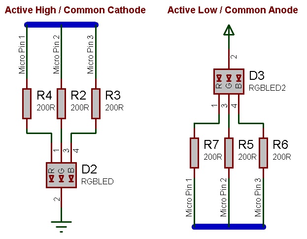
An active high LED will light when the microcontroller pin is outputting a logic 1 and be off when the microcontroller pin is outputting a logic 0 or in input mode.
An active low LED will light when the microcontroller pin is outputting a logic 0 and be off when the microcontroller pin is outputting a logic 1 or in input mode.
Six pin tricolour LEDs can simply be treated as three individual standards LEDs.
The series resistor acts to protect each individual LED from damage due to excess current. The value of resistor used can be changed based on the brightness of the LED and power consumption. Usually the three colour LEDs have different characteristics from each other so a different protection resistor should be provided for each LED to balance the LEDs output.
This LED Calculator tool is a good resource for calculating the correct LED series protection resistor.
LED Resistor Calculator Tool
This example for the RGB LED uses three analogue sliders to set the output colour of the LED.
 RGB LED Example
The LED Colour is output to the LED using the Timer interrupt which calls the RGB LED Tick function.
The RGB LED properties include a setting for "Colour Bit Size" which sets the period for the LED colour PWM. The "Rollover Value" property shows the number of interrupts required for each PWM period so the timer interrupt should be running fast enough to allow the LED to output several periods per second. Persistence of vision can normally no longer detect any flickering light above approx 24Hz.
For a constant none flickering LED you can work out the minimum interrupt frequency like this.
30Hz * Rollover Value = Minimum interrupt frequency
30Hz * 256 = 7680Hz
60Hz * 64 = 3840Hz
Each LED colour channel can be set from 0 (minimum) to the rollover value - 1 (maximum). Therefore with a colour channel bit size of 8 there are theoretically 16777216 colours available 2^(8*3). With a colour bit size of 4 the available number of colours that can be generated drops to 4096, 2^(4*3).
Downloadable macro reference

|
Disable
|
| Disables the RGB LED. It will no longer respond to color changes.
|
 - VOID - VOID
|
Return
|
|
|
Enable
|
| Enables the RGB LED. This must be done before the LED can be lit or the color changed.
|
| - VOID
|
Return
|
|
|
Tick
|
| Call this macro at regular intervals to illuminate the LED with the chosen color. Turns each pin on and off to generate a simple PWM signal for each color - when done rapidly, this gives the illusion of the chosen color.
|
| - VOID
|
Return
|
|
|
SetColor
|
| Set the target color for the LED. Each of the Red, Blue and Green channels can be set to any value from 0 (off) to 255 (full brightness).
|
 - BYTE - BYTE
|
red
|
| Red component of RGB LED local to this macro
|
| - BYTE
|
green
|
| Green component of RGB LED local to this macro
|
| - BYTE
|
blue
|
| Blue component of RGB LED local to this macro
|
| - VOID
|
Return
|
Property reference

|
Properties
|

|
Pin Connections
|

|
Red
|
| Pin that the red LED is connected to.
|
|
|
Green
|
| Pin that the green LED is connected to.
|
|
|
Blue
|
| Pin tha the Blue pin is connected to.
|
|
|
Misc
|

|
Polarity
|
| Active High: Use for common cathode LEDs - Pin true = LED On. Active Low: Use for common anode LEDs - Pin false = LED On.
|
|
|
Color bit size
|
| Color bit depth. Sets the resolution of the virtual PWM signals driving the LEDs. Lower values mean that the 'Tick' macro can be called less often, but reduced the number of colours that can be created.
|

|
Rollover value
|
| The number of unique colours each R/G/B channel can output. Range: 0 to (Rollover Value - 1).
|
|
|
Simulation
|

|
Target
|
| Create custom LED shapes by pointing this property at any object on your panel. This also works with groups of objects - all children of the group will change color.
|
|
|
Shape
|
| Choose a simple shape for the LED when there is no 'Target' selected.
|

|
Width
|
| Width of the LED shape.
|
|
|
Height
|
| Height of the LED shape.
|
|
|
Depth
|
| Depth of the LED shape.
|
