Difference between revisions of "Component: IO Expander (Comms: System)"
(Created page with "{| style="width:50%" |- | width="20%" style="color:gray;" | Author | Matrix TSL |- | width="20%" style="color:gray;" | Version | 1.0 |- | width="20%" style="color:gray...") |
|||
| Line 13: | Line 13: | ||
==IO Expander component== | ==IO Expander component== | ||
| − | Provides 16 digital input/output pins arranged into two 8-bit ports using a | + | Provides 16 digital input/output pins arranged into two 8-bit ports using a SPI bus connection. Multiple expanders can be connected to the same SPI peripheral by means of individual chip select pins. |
==Detailed description== | ==Detailed description== | ||
| + | |||
| + | |||
''No detailed description exists yet for this component'' | ''No detailed description exists yet for this component'' | ||
| + | |||
| + | |||
==Examples== | ==Examples== | ||
| + | |||
| + | |||
| Line 54: | Line 60: | ||
[[File:DS1307Ram.jpg]] | [[File:DS1307Ram.jpg]] | ||
| + | |||
| + | |||
| Line 234: | Line 242: | ||
|- | |- | ||
| width="10%" align="center" style="background-color:#D8C9D8;" align="center" | [[File:Fc9-comp-macro.png]] | | width="10%" align="center" style="background-color:#D8C9D8;" align="center" | [[File:Fc9-comp-macro.png]] | ||
| − | | width="90%" style="background-color:#D8C9D8; color:#4B008D;" | ''' | + | | width="90%" style="background-color:#D8C9D8; color:#4B008D;" | '''WriteRegister''' |
|- | |- | ||
| − | | colspan="2" | | + | | colspan="2" | Writes an 8-bit value to a register on the I/O expander device. |
|- | |- | ||
|- | |- | ||
| Line 242: | Line 250: | ||
| width="90%" | Address | | width="90%" | Address | ||
|- | |- | ||
| − | | colspan="2" | Range: 0- | + | | colspan="2" | Register address to write to. Range: 0-15 |
| + | |- | ||
| + | | width="10%" align="center" | [[File:Fc9-u8-icon.png]] - BYTE | ||
| + | | width="90%" | Value | ||
| + | |- | ||
| + | | colspan="2" | Value to write. Range: 0-255 | ||
|- | |- | ||
| width="10%" align="center" style="border-top: 2px solid #000;" | [[File:Fc9-void-icon.png]] - VOID | | width="10%" align="center" style="border-top: 2px solid #000;" | [[File:Fc9-void-icon.png]] - VOID | ||
| Line 252: | Line 265: | ||
|- | |- | ||
| width="10%" align="center" style="background-color:#D8C9D8;" align="center" | [[File:Fc9-comp-macro.png]] | | width="10%" align="center" style="background-color:#D8C9D8;" align="center" | [[File:Fc9-comp-macro.png]] | ||
| − | | width="90%" style="background-color:#D8C9D8; color:#4B008D;" | ''' | + | | width="90%" style="background-color:#D8C9D8; color:#4B008D;" | '''Initialise''' |
|- | |- | ||
| − | | colspan="2" | | + | | colspan="2" | |
|- | |- | ||
| − | |||
| − | |||
| − | |||
| − | |||
| − | |||
| − | |||
| − | |||
| − | |||
| − | |||
| − | |||
|- | |- | ||
| width="10%" align="center" style="border-top: 2px solid #000;" | [[File:Fc9-void-icon.png]] - VOID | | width="10%" align="center" style="border-top: 2px solid #000;" | [[File:Fc9-void-icon.png]] - VOID | ||
| Line 355: | Line 358: | ||
| width="90%" | Channel | | width="90%" | Channel | ||
|- | |- | ||
| − | | colspan="2" | Channel | + | | colspan="2" | SPI Channel selector |
|- | |- | ||
| − | | width="10%" align="center" | [[File:Fc9-type- | + | | width="10%" align="center" | [[File:Fc9-type-16-icon.png]] |
| − | | width="90%" | | + | | width="90%" | Prescale |
|- | |- | ||
| − | | colspan="2" | | + | | colspan="2" | Prescale option selector |
|- | |- | ||
| − | | width="10%" align="center" | [[File:Fc9-type- | + | | width="10%" align="center" | [[File:Fc9-type-5-icon.png]] |
| − | | width="90%" | | + | | width="90%" | MOSI |
|- | |- | ||
| − | | colspan="2" | | + | | colspan="2" | SPI Data Out Pin SDO - Also Known as Master Out Slave In (MOSI) when used in Master mode. |
|- | |- | ||
| − | | width="10%" align="center" | [[File:Fc9-type- | + | | width="10%" align="center" | [[File:Fc9-type-5-icon.png]] |
| − | | width="90%" | | + | | width="90%" | MISO |
|- | |- | ||
| − | | colspan="2" | | + | | colspan="2" | SPI Data In Pin SDI - Also Known as Master In Slave Out (MISO) when used in Master mode. |
|- | |- | ||
| width="10%" align="center" | [[File:Fc9-type-5-icon.png]] | | width="10%" align="center" | [[File:Fc9-type-5-icon.png]] | ||
| − | | width="90%" | | + | | width="90%" | CLK |
|- | |- | ||
| − | | colspan="2" | Pin | + | | colspan="2" | SPI Clock Pin CLK - The Clock signal is driven by the SPI master. |
|- | |- | ||
| width="10%" align="center" | [[File:Fc9-type-5-icon.png]] | | width="10%" align="center" | [[File:Fc9-type-5-icon.png]] | ||
| − | | width="90%" | | + | | width="90%" | CS / SS |
|- | |- | ||
| − | | colspan="2" | Pin used | + | | colspan="2" | Chip Select / Slave Select Pin Master Mode: General purpose output pin used to select the remote SPI device. Slave Mode: Hardware chip select pin input used to select the SPI device. |
|- | |- | ||
| width="10%" align="center" | [[File:Fc9-type-7-icon.png]] | | width="10%" align="center" | [[File:Fc9-type-7-icon.png]] | ||
Latest revision as of 15:07, 31 August 2021
| Author | Matrix TSL |
| Version | 1.0 |
| Category | Comms: System |
Contents
IO Expander component
Provides 16 digital input/output pins arranged into two 8-bit ports using a SPI bus connection. Multiple expanders can be connected to the same SPI peripheral by means of individual chip select pins.
Detailed description
No detailed description exists yet for this component
Examples
More information on I2C can be found here,
Matrix Flowcode Blog: Simplified communications I2C and SPI
Generic I2C EEPROM
Example file demonstrating how to read and write bytes from a generic I2C EEPROM device.
![]() I2CEEPROM
I2CEEPROM
Simulated I2C devices
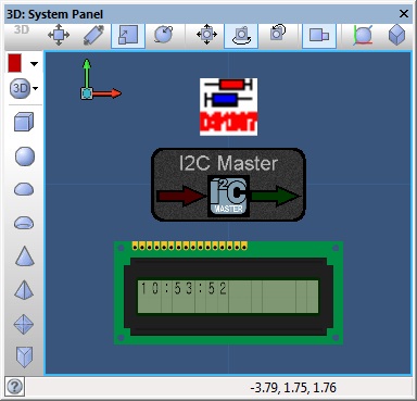
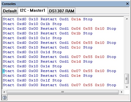
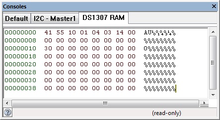
This example uses the I2C master component combined with the DS1307 injector to simulate an I2C communications bus between the target Microcontroller and the virtual DS1307 device.
![]() I2C DS1307 Example
The panel displays the current time from the DS1307 RAM which is populated to match the system time.
I2C DS1307 Example
The panel displays the current time from the DS1307 RAM which is populated to match the system time.
The I2C console shows the communications between the target microcontroller and simulated I2C device.
The DS1307 console shows the contents of RAM memory on the simulated I2C device.
Downloadable macro reference
| ReadRegister | |
| Reads an 8-bit value from a register on the I/O expander device. | |
| Address | |
| Register address to write to. Range: 0-15 | |
| Return | |
| WriteRegister | |
| Writes an 8-bit value to a register on the I/O expander device. | |
| Address | |
| Register address to write to. Range: 0-15 | |
| Value | |
| Value to write. Range: 0-255 | |
| Return | |
| Initialise | |
| Return | |
| Initialise | |
| Return | |
| Initialise | |
| Enables the I²C hardware and performs some initialization. Should be called at the start of the program or at least before any of the other I²C functions are called. | |
| Return | |
| CheckNetworkStatus | |
| Returns the state of the GSM network. 0 = Not connected, 1 = connected, 255 = no reply from GSM. | |
| Return | |
| CheckForIncoming | |
| Checks to see if any incoming phone call or SMS message. 0 = Nothing, 1 = Text Received, 2 = Phone Ringing | |
| Return | |
| Initialise | |
| Sets up the GSM module. Returns 0 for OK, 255 for no reply and 254 for command fail. | |
| Return | |


