Difference between revisions of "Component: Fast Fourier Transform (FFT) (DSP)"
(XML import BR) |
|||
| Line 21: | Line 21: | ||
==Examples== | ==Examples== | ||
| − | |||
Example takes 256 analogue readings using an ADC input and then passes the collection of 256 samples to the FFT function which produces 128 individual frequency banks which are then plotted from left (lowest frequency) to right (highest frequency) on the graphical LCD. | Example takes 256 analogue readings using an ADC input and then passes the collection of 256 samples to the FFT function which produces 128 individual frequency banks which are then plotted from left (lowest frequency) to right (highest frequency) on the graphical LCD. | ||
| − | |||
{{Fcfile|FFT_Test.fcfx|FFT Example}} | {{Fcfile|FFT_Test.fcfx|FFT Example}} | ||
| − | |||
| − | |||
Frequency output for a set of data | Frequency output for a set of data | ||
| Line 52: | Line 48: | ||
[[File:FFTBanks.jpg]] | [[File:FFTBanks.jpg]] | ||
| − | |||
==Downloadable macro reference== | ==Downloadable macro reference== | ||
Revision as of 15:45, 16 February 2017
| Author | Matrix Ltd |
| Version | 1.2 (Release) |
| Category | DSP |
Contents
 Fast Fourier Transform (FFT) component
Provides a way of converting a buffer full of time domain data into frequency domain data. The output of the FFT is a set of frequency bins which correspond to the frequencies present in the signal. The number of frequency bins is equal to half the input buffer size with each bin being responsible for a portion of the frequency up to 1/2 the nyquist.
Examples
Example takes 256 analogue readings using an ADC input and then passes the collection of 256 samples to the FFT function which produces 128 individual frequency banks which are then plotted from left (lowest frequency) to right (highest frequency) on the graphical LCD.
![]() FFT Example
Frequency output for a set of data
FFT Example
Frequency output for a set of data
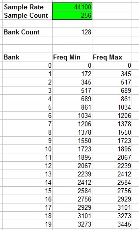
Frequency banks can be worked out by using the sample frequency and buffer size. The number of frequency banks is equal to the number of samples divided by 2 minus 1. We subtract the one because bank 0 is always empty and so can be discounted.
FrequencyBanks = (SampleCount / 2) - 1
The frequency ranges present inside a bank can be worked out as follows.
FreqMin = ((SampleRate / 2) / (SampleCount / 2)) * Bank
FreqMax = ((SampleRate / 2) / (SampleCount / 2)) * (Bank + 1)
For example if we sample at 44.1KHz and collect 256 samples then frequency bank 10 would represent any frequencies in the range of 1723Hz to 1895Hz.
Here is a spreadsheet document that will calculate the frequencies present in each bank. The highlighted green fields are editable and will update the rest of the values.
File:FFT Frequency Bank Calculator.xls
Downloadable macro reference
ReadFrequencyBank
Reads the value from one of the frequency banks after the FFT conversion has been performed.
Valid frequency banks range from 1 to the allocated buffer size / 2 assuming the buffers are sized to be equal to a power of 2.
Parameters
- UINT BankIdx
Return value
FFT
Performs the data conversion from time based data to frequency based data.
Takes the Input and converts it into real and imaginary frequency data ready for you to read the individual frequency bins.
Parameters
- This macro has no parameters
Return value
- This call does not return a value
Simulation macro reference
This component does not contain any simulation macros
Property reference
Buffer Manager
This property is of type Fixed list of ints and can be referenced with the variable name buffer_manager.
DSP buffer manager assigned to the component.
Input
This property is of type Fixed list of ints and can be referenced with the variable name input_a.
Time based inputs, signal data should be signed and centered around the 0 position so it goes positive and negative.
Output Real
This property is of type Fixed list of ints and can be referenced with the variable name output_c.
The Real portion of the FFT conversion data.
The Real and Imaginary data are combined to provide frequency bank readings such as amplitude and phase.
Output Imaginary
This property is of type Fixed list of ints and can be referenced with the variable name output_i.
The Imaginary portion of the FFT conversion data.
The Real and Imaginary data are combined to provide frequency bank readings such as amplitude and phase.
Filter Input Data
This property is of type True or false and can be referenced with the variable name filterdata.
Applies a hamming window filter to the time domain sample data to provide better frequency detection.
Sample Rate
This property is of type Floating point and can be referenced with the variable name sample_rate.
Sample rate used to perform simple calculations like nyquist and bin size.
Nyquist Frequency
This property is of type Floating point and can be referenced with the variable name nyquist.
The maximum frequency that can theoretically be detected by the FFT component assuming the sample rate is setup correctly.
Frequency Bin Count
This property is of type Signed integer and can be referenced with the variable name bin_count.
The number of frequency bins that the component will provide.
Frequency Bin Size (Hz)
This property is of type Floating point and can be referenced with the variable name bin_size.
The frequency range covered by each frequency bin.

