|
|
| Line 16: |
Line 16: |
| | | | |
| | ==Detailed description== | | ==Detailed description== |
| | + | |
| | + | |
| | | | |
| | | | |
| Line 22: |
Line 24: |
| | | | |
| | ==Examples== | | ==Examples== |
| | + | |
| | + | |
| | | | |
| | | | |
| Line 139: |
Line 143: |
| | |- | | |- |
| | | colspan="2" | | | | colspan="2" | |
| − | |-
| |
| − | | width="10%" align="center" style="border-top: 2px solid #000;" | [[File:Fc9-void-icon.png]] - VOID
| |
| − | | width="90%" style="border-top: 2px solid #000;" | ''Return''
| |
| − | |}
| |
| − |
| |
| − |
| |
| − | {| class="wikitable" style="width:60%; background-color:#FFFFFF;"
| |
| − | |-
| |
| − | | width="10%" align="center" style="background-color:#D8C9D8;" align="center" | [[File:Fc9-comp-macro.png]]
| |
| − | | width="90%" style="background-color:#D8C9D8; color:#4B008D;" | '''ReceiveString'''
| |
| − | |-
| |
| − | | colspan="2" | Gets a string from the receive buffer
| |
| − | |-
| |
| − | |-
| |
| − | | width="10%" align="center" | [[File:Fc9-u16-icon.png]] - UINT
| |
| − | | width="90%" | MaxChars
| |
| − | |-
| |
| − | | colspan="2" |
| |
| − | |-
| |
| − | | width="10%" align="center" | [[File:Fc9-u16-icon.png]] - UINT
| |
| − | | width="90%" | Timeout
| |
| − | |-
| |
| − | | colspan="2" | Time in milliseconds to wait for data
| |
| − | |-
| |
| − | | width="10%" align="center" style="border-top: 2px solid #000;" | [[File:Fc9-string-icon.png]] - STRING
| |
| − | | width="90%" style="border-top: 2px solid #000;" | ''Return''
| |
| − | |}
| |
| − |
| |
| − |
| |
| − | {| class="wikitable" style="width:60%; background-color:#FFFFFF;"
| |
| − | |-
| |
| − | | width="10%" align="center" style="background-color:#D8C9D8;" align="center" | [[File:Fc9-comp-macro.png]]
| |
| − | | width="90%" style="background-color:#D8C9D8; color:#4B008D;" | '''Initialise'''
| |
| − | |-
| |
| − | | colspan="2" | Initialises the UART component pins ready to send and receive data
| |
| − | |-
| |
| − | |-
| |
| − | | width="10%" align="center" style="border-top: 2px solid #000;" | [[File:Fc9-void-icon.png]] - VOID
| |
| − | | width="90%" style="border-top: 2px solid #000;" | ''Return''
| |
| − | |}
| |
| − |
| |
| − |
| |
| − | {| class="wikitable" style="width:60%; background-color:#FFFFFF;"
| |
| − | |-
| |
| − | | width="10%" align="center" style="background-color:#D8C9D8;" align="center" | [[File:Fc9-comp-macro.png]]
| |
| − | | width="90%" style="background-color:#D8C9D8; color:#4B008D;" | '''ReceiveString'''
| |
| − | |-
| |
| − | | colspan="2" | Receives a string of bytes and returns the number of bytes received.
| |
| − | |-
| |
| − | |-
| |
| − | | width="10%" align="center" | [[File:Fc9-string-icon.png]] - STRING
| |
| − | | width="90%" | StringData
| |
| − | |-
| |
| − | | colspan="2" |
| |
| − | |-
| |
| − | | width="10%" align="center" | [[File:Fc9-u16-icon.png]] - UINT
| |
| − | | width="90%" | NumBytes
| |
| − | |-
| |
| − | | colspan="2" | Maximum number of bytes to try and receive
| |
| − | |-
| |
| − | | width="10%" align="center" | [[File:Fc9-u16-icon.png]] - UINT
| |
| − | | width="90%" | Timeout
| |
| − | |-
| |
| − | | colspan="2" | Max amount of time in ms to wait between bytes
| |
| − | |-
| |
| − | | width="10%" align="center" style="border-top: 2px solid #000;" | [[File:Fc9-u8-icon.png]] - BYTE
| |
| − | | width="90%" style="border-top: 2px solid #000;" | ''Return''
| |
| − | |}
| |
| − |
| |
| − |
| |
| − | {| class="wikitable" style="width:60%; background-color:#FFFFFF;"
| |
| − | |-
| |
| − | | width="10%" align="center" style="background-color:#D8C9D8;" align="center" | [[File:Fc9-comp-macro.png]]
| |
| − | | width="90%" style="background-color:#D8C9D8; color:#4B008D;" | '''Start'''
| |
| − | |-
| |
| − | | colspan="2" | Startup routine required by the hardware device. Automatically clears the display after initialising.
| |
| − | |-
| |
| − | |-
| |
| − | | width="10%" align="center" style="border-top: 2px solid #000;" | [[File:Fc9-void-icon.png]] - VOID
| |
| − | | width="90%" style="border-top: 2px solid #000;" | ''Return''
| |
| − | |}
| |
| − |
| |
| − |
| |
| − | {| class="wikitable" style="width:60%; background-color:#FFFFFF;"
| |
| − | |-
| |
| − | | width="10%" align="center" style="background-color:#D8C9D8;" align="center" | [[File:Fc9-comp-macro.png]]
| |
| − | | width="90%" style="background-color:#D8C9D8; color:#4B008D;" | '''SetLEDState'''
| |
| − | |-
| |
| − | | colspan="2" | Sets the state of a single LED
| |
| − | |-
| |
| − | |-
| |
| − | | width="10%" align="center" | [[File:Fc9-u8-icon.png]] - BYTE
| |
| − | | width="90%" | Port
| |
| − | |-
| |
| − | | colspan="2" | 0 = PortA, 1 = PortB
| |
| − | |-
| |
| − | | width="10%" align="center" | [[File:Fc9-u8-icon.png]] - BYTE
| |
| − | | width="90%" | LED
| |
| − | |-
| |
| − | | colspan="2" | 0 = LED0, 7 = LED7
| |
| − | |-
| |
| − | | width="10%" align="center" | [[File:Fc9-u8-icon.png]] - BYTE
| |
| − | | width="90%" | State
| |
| − | |-
| |
| − | | colspan="2" |
| |
| − | |-
| |
| − | | width="10%" align="center" style="border-top: 2px solid #000;" | [[File:Fc9-void-icon.png]] - VOID
| |
| − | | width="90%" style="border-top: 2px solid #000;" | ''Return''
| |
| − | |}
| |
| − |
| |
| − |
| |
| − | {| class="wikitable" style="width:60%; background-color:#FFFFFF;"
| |
| − | |-
| |
| − | | width="10%" align="center" style="background-color:#D8C9D8;" align="center" | [[File:Fc9-comp-macro.png]]
| |
| − | | width="90%" style="background-color:#D8C9D8; color:#4B008D;" | '''GetRxIdent'''
| |
| − | |-
| |
| − | | colspan="2" | Gets the Rx ID as a Integer Standard and Extended IDs.
| |
| − | |-
| |
| − | |-
| |
| − | | width="10%" align="center" | [[File:Fc9-u8-icon.png]] - BYTE
| |
| − | | width="90%" | Buffer
| |
| − | |-
| |
| − | | colspan="2" |
| |
| − | |-
| |
| − | | width="10%" align="center" style="border-top: 2px solid #000;" | [[File:Fc9-u32-icon.png]] - ULONG
| |
| − | | width="90%" style="border-top: 2px solid #000;" | ''Return''
| |
| − | |}
| |
| − |
| |
| − |
| |
| − | {| class="wikitable" style="width:60%; background-color:#FFFFFF;"
| |
| − | |-
| |
| − | | width="10%" align="center" style="background-color:#D8C9D8;" align="center" | [[File:Fc9-comp-macro.png]]
| |
| − | | width="90%" style="background-color:#D8C9D8; color:#4B008D;" | '''Initialise'''
| |
| − | |-
| |
| − | | colspan="2" | Must be called before any other CAN component macros to enable and initialise the CAN peripheral.
| |
| − | |-
| |
| | |- | | |- |
| | | width="10%" align="center" style="border-top: 2px solid #000;" | [[File:Fc9-void-icon.png]] - VOID | | | width="10%" align="center" style="border-top: 2px solid #000;" | [[File:Fc9-void-icon.png]] - VOID |
| Author
|
Matrix Ltd
|
| Version
|
1.2
|
| Category
|
DSP
|
Level component
Allows for detection and collection of peaks, troughs and averages.
Detailed description
No detailed description exists yet for this component
Examples
Here is a basic example of the Level component. The example collects the max, min and average readings from the buffer and displays them on the LCD display.
 Level
Level
The values in the buffer are defined using the InputADC component.
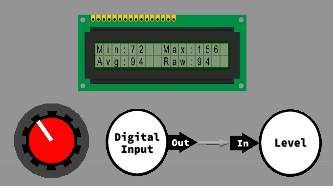
Min: Minimum (smallest) value read from the buffer.
Max: Maximum (largest) value read from the buffer.
Average: Rolling average calculated from the values inside the buffer.
Downloadable macro reference

|
ReadTroughArray
|
| Returns the lowest value from the last "Decay" number of buffers.
|
 - UINT - UINT
|
Return
|
|
|
ReadTrough
|
| Returns the lowest value from the last "Decay" number of index locations.
|
| [[File:]] -
|
Return
|
|
|
ReadAverage
|
| Returns the average from the last "Decay" number of index locations.
|
| [[File:]] -
|
Return
|
|
|
ReadPeakArray
|
| Returns the highest value from the last "Decay" number of buffers.
|
| - UINT
|
Return
|
|
|
ReadAverageArray
|
| Returns the average from the last "Decay" number of buffers.
|
| - UINT
|
Return
|
|
|
ReadPeak
|
| Returns the highest value from the last "Decay" number of index locations.
|
| [[File:]] -
|
Return
|
|
|
ResetRecords
|
| Allows the peak and trough to be reset back to default values.
|
| [[File:]] -
|
ResetPeak
|
|
|
| [[File:]] -
|
ResetTrough
|
|
|
 - VOID - VOID
|
Return
|
Property reference

|
Properties
|

|
Connect To
|
| DSP component with output buffer to collect our data from.
|

|
Decay on Peak/Trough
|
| Yes - The Peak and Trough value will only be maintained for the decay number of buffers. No - The record Peak and Trough values will be maintained until reset.
|

|
Decay
|
| Configures how many buffers or values to allow a record to persist
|

|
Connections
|
|
|
Simulations
|
