Difference between revisions of "Component: LED (SMD, PCB) ()"
(Created page with "{| style="width:50%" |- | width="20%" style="color:gray;" | Author | Matrix Ltd |- | width="20%" style="color:gray;" | Version | 1.1 |- | width="20%" style="color:gray...") |
|||
| Line 25: | Line 25: | ||
==Examples== | ==Examples== | ||
| − | + | ||
| + | LEDs can be wired either active high or active low. The LED components should each have a property allowing you to configure which LED type your using. | ||
| + | |||
| + | [[File:LED_Active.jpg]] | ||
| + | |||
| + | |||
| + | An active high LED will light when the microcontroller pin is outputting a logic 1 and be off when the microcontroller pin is outputting a logic 0 or in input mode. | ||
| + | |||
| + | |||
| + | An active low LED will light when the microcontroller pin is outputting a logic 0 and be off when the microcontroller pin is outputting a logic 1 or in input mode. | ||
| + | |||
| + | |||
| + | The series resistor can be on either side of the LED and acts to protect the LED from damage due to excess current. The value of resistor used can be changed based on the brightness of the LED and power consumption. | ||
| + | |||
| + | |||
| + | This LED Calculator tool is a good resource for calculating the correct LED series protection resistor. | ||
| + | |||
| + | [https://www.digikey.co.uk/en/resources/conversion-calculators/conversion-calculator-led-series-resistor LED Resistor Calculator Tool] | ||
==Downloadable macro reference== | ==Downloadable macro reference== | ||
Revision as of 16:02, 10 February 2022
| Author | Matrix Ltd |
| Version | 1.1 |
| Category |
Contents
LED (SMD, PCB) component
Surface mount LED in standard PLCC2 package. Colour can be set friom component properties.
Component Pack
FREE
Detailed description
No detailed description exists yet for this component
Examples
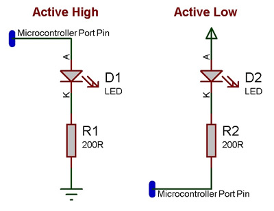
LEDs can be wired either active high or active low. The LED components should each have a property allowing you to configure which LED type your using.
An active high LED will light when the microcontroller pin is outputting a logic 1 and be off when the microcontroller pin is outputting a logic 0 or in input mode.
An active low LED will light when the microcontroller pin is outputting a logic 0 and be off when the microcontroller pin is outputting a logic 1 or in input mode.
The series resistor can be on either side of the LED and acts to protect the LED from damage due to excess current. The value of resistor used can be changed based on the brightness of the LED and power consumption.
This LED Calculator tool is a good resource for calculating the correct LED series protection resistor.
