Difference between revisions of "Component: LED Matrix (Serial) (LEDs)"
(Created page with "{| style="width:50%" |- | width="20%" style="color:gray;" | Author | Matrix Ltd |- | width="20%" style="color:gray;" | Version | 1.1 |- | width="20%" style="color:gray...") |
|||
| Line 20: | Line 20: | ||
==Detailed description== | ==Detailed description== | ||
| + | |||
| + | |||
''No detailed description exists yet for this component'' | ''No detailed description exists yet for this component'' | ||
==Examples== | ==Examples== | ||
| + | |||
| + | |||
| Line 169: | Line 173: | ||
| colspan="2" | Allows the column and text data sent to the display to be flipped | | colspan="2" | Allows the column and text data sent to the display to be flipped | ||
|- | |- | ||
| − | + | | width="10%" align="center" style="background-color:#EAE1EA;" | [[File:Fc9-conn-icon.png]] | |
| − | + | | width="90%" style="background-color:#EAE1EA; color:#4B008D;" | Connections | |
| − | |||
| − | |||
| − | |||
| − | |||
| − | |||
| − | |||
| − | |||
| − | |||
| − | | width="10%" align="center" style="background-color:# | ||
| − | | width="90%" style="background-color:# | ||
|- | |- | ||
|- | |- | ||
| Line 208: | Line 202: | ||
| colspan="2" | Reset pin used to clear all of the states in the external buffer IC's | | colspan="2" | Reset pin used to clear all of the states in the external buffer IC's | ||
|- | |- | ||
| − | | width="10%" align="center" style="background-color:# | + | | width="10%" align="center" style="background-color:#EAE1EA;" | [[File:Fc9-conn-icon.png]] |
| − | | width="90%" style="background-color:# | + | | width="90%" style="background-color:#EAE1EA; color:#4B008D;" | Colours |
| + | |- | ||
| + | |- | ||
| + | | width="10%" align="center" | [[File:Fc9-type-1-icon.png]] | ||
| + | | width="90%" | On Color | ||
| + | |- | ||
| + | | colspan="2" | Simulated colour of the LEDs when switched On | ||
| + | |- | ||
| + | | width="10%" align="center" | [[File:Fc9-type-1-icon.png]] | ||
| + | | width="90%" | Off Color | ||
| + | |- | ||
| + | | colspan="2" | Simulated colour of the LEDs when switched Off | ||
| + | |- | ||
| + | | width="10%" align="center" style="background-color:#EAE1EA;" | [[File:Fc9-conn-icon.png]] | ||
| + | | width="90%" style="background-color:#EAE1EA; color:#4B008D;" | Simulation | ||
|- | |- | ||
|- | |- | ||
Latest revision as of 17:27, 9 November 2022
| Author | Matrix Ltd |
| Version | 1.1 |
| Category | LEDs |
Contents
LED Matrix (Serial) component
LED Matrix component designed to work using a single data and clock pin. Each LED on the display can be controlled in a chain by setting the data appropriatley and then generating the appropriate amount of clock pulses.
Component Pack
BASICIO
Detailed description
No detailed description exists yet for this component
Examples
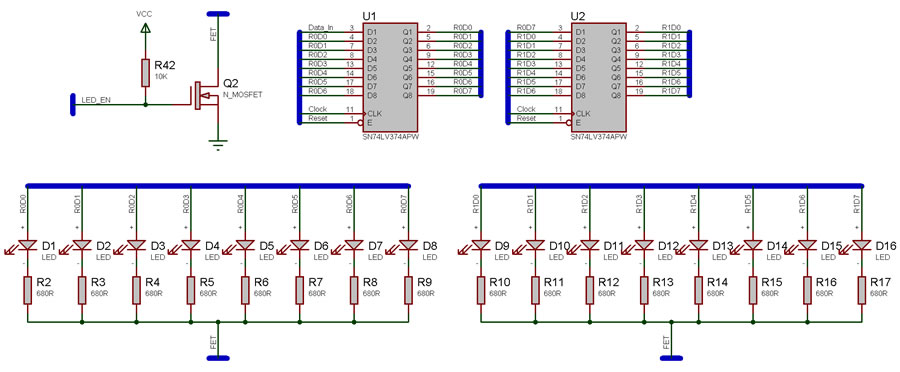
Serial LED matrix example schematic showing 16 LEDs connected using two octal buffer ICs. Data connections to the microcontroller are Data_In, LED_EN, Clock and Reset.
Each clock pulse transfers the output state to the next LED so Data_In goes to LED R0D0 and LED R0D0 goes to LED R0D1 etc.
Example Program
![]() ledmatrixs
Note. to allow the simulation to run smoothly ensure that the simulation speed is set to normal and you may also want to enable hardware acceleration using the Global Options.
ledmatrixs
Note. to allow the simulation to run smoothly ensure that the simulation speed is set to normal and you may also want to enable hardware acceleration using the Global Options.
Example Panel Display
Downloadable macro reference
| StrobeHigh | |
| Sets the strobe pin high. Strobing controls the LED brightness and does not apply to simulation. | |
| Return | |
| StrobeLow | |
| Sets the strobe pin low. Strobing controls the LED brightness and does not apply to simulation. | |
| Return | |
| ClearLEDs | |
| Sets all of the LEDs in the matrix to the off state. | |
| Return | |
| WriteColumn | |
| Allows a single column of data to be inserted, Acts to shift the rest of the columns across by one. | |
| Data | |
| Data to display on the column of LEDs | |
| Return | |

