Component: 7Segment (Quad) (Segment)

From Flowcode Help
Revision as of 17:27, 9 November 2022 by Wiki bot (talk | contribs)
(diff) ← Older revision | Latest revision (diff) | Newer revision → (diff)
Jump to navigationJump to search
Author Matrix Ltd
Version 1.2
Category Segment


7Segment (Quad) component

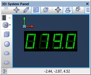
14mm seven segment display. LED colour can be set from properties.

Component Pack

FREE

Detailed description

No detailed description exists yet for this component

Examples

Each segment will require a current limiting resistor.

This LED Calculator tool is a good resource for calculating the correct LED series protection resistor.

LED Resistor Calculator Tool


Basic Multiplexing

Only one of the four 7-segment LEDs can be enabled at a time so we need a way of multiplexing the output so that we can display a number on all four LEDs. To do this we switch between LED outputs at fairly high speed and persistence of vision allows the display to appear fixed and constant.

This example demonstrates a very basic loop to display a four digit number multiplexed across four 7segment displays. FC6 Icon.png Quad 7Segment Display Example

Timer Based Multiplexing

This example demonstrates a timer interrupt to display a four digit number multiplexed across four 7segment displays. The timer interrupt takes care of updating the display leaving our program free to count up in 100ms increments. FC6 Icon.png Quad 7Segment Display Example 2 The panel should show the simulation run time down to the current tenth of a second.

QuadSegCount.jpg

Stop Watch

This next example uses a timer interrupt to multiplex between the displays and a second timer interrupt to count the passing of time allowing for accurate timings. Using four single 7-seg components we create a timer capable of monitoring time from 0.0 to 999.9 seconds in multiples of 100ms. The second timer interrupt flags to the main when the count value has changed allowing the heavier calculations to extract the digits from the counter to be done outside of the high speed interrupt routine and therefore maintain accurate timing.

Switches connected to Port D allow for the timer to be started, stopped and reset. FC6 Icon.png 7Segment Timer

Downloadable macro reference
Fc9-comp-macro.png ShowSegments
Allows the individual segments of the display to be controlled. 
Fc9-u8-icon.png - BYTE Digit
Which of the four digits to change. (0...3) 
Fc9-u8-icon.png - BYTE Segments
8-bit Binary value to set the segments, bit0 = segA, bit1 = segB... 
Fc9-void-icon.png - VOID Return


Fc9-comp-macro.png ShowDigit
Set the number and decimal point to be displayed in the given digit of the display. 
Fc9-u8-icon.png - BYTE Digit
Which of the four digits to change. (0...3) 
Fc9-u8-icon.png - BYTE Value
The number value to set the digit to (0...15), 16=Clear 
Fc9-u8-icon.png - BYTE DecimalPoint
Whether to show the decimal point for the chosen digit. 
Fc9-void-icon.png - VOID Return


Property reference

Fc9-prop-icon.png Properties
Fc9-type-16-icon.png Display Type
Set this according to the specification of your hardware display. Common Anode: Pin true -> LED Off, Pin false -> LED On Common Cathode: Pin true -> LED On, Pin false -> LED Off 
Fc9-type-16-icon.png Common Type
The state of the output common pin when the 7-segment display is active. Usually a common cathode display uses a low signal and a common anode uses a high signal. If the common pin is routed via a transistor for power amplification then the signal may need to be reversed. 
Fc9-type-7-icon.png Show Seg Labels
Show segment name labels overlayed over the component. 
Fc9-conn-icon.png Connections
Fc9-type-5-icon.png Common Pin 0
Pin to enable the first digit. 
Fc9-type-5-icon.png Common Pin 1
Pin to enable the second digit. 
Fc9-type-5-icon.png Common Pin 2
Pin to enable the third digit. 
Fc9-type-5-icon.png Common Pin 3
Pin to enable the fourth digit. 
Fc9-type-5-icon.png Pin0 (A)
Pin for the 'A' segments of the displays. 
Fc9-type-5-icon.png Pin1 (B)
Pin for the 'B' segments of the displays. 
Fc9-type-5-icon.png Pin2 (C)
Pin for the 'C' segments of the displays. 
Fc9-type-5-icon.png Pin3 (D)
Pin for the 'D' segments of the displays. 
Fc9-type-5-icon.png Pin4 (E)
Pin for the 'E' segments of the displays. 
Fc9-type-5-icon.png Pin5 (F)
Pin for the 'F' segments of the displays. 
Fc9-type-5-icon.png Pin6 (G)
Pin for the 'G' segments of the displays. 
Fc9-type-5-icon.png Pin7 (DP)
Pin for the decimal points of the displays. 
Fc9-conn-icon.png Colors
Fc9-type-1-icon.png LED Color
Color of the LED segments when truned on. When off, they use a much darker shade of the same hue. 
Fc9-type-1-icon.png Body Color
Color of the plastic casing containing the LEDs. 
Fc9-type-1-icon.png Label Color
Color for the optional LED segment labels.