Page 2 of 3
Re: One Wire Example - Failure on linking
Posted: Wed Oct 21, 2009 11:16 am
by Benj
Hello Eric
I have just tested your program running on a 16F877A clocked at 19.6608MHz.
I had to reconfigure the LCD Connections to switch these to PortB and also to allow the connections to match the EB005 LCD E-Block. I also dropped the device count to 2 in the main routine so I didn't get an incorrect device count error. After doing this I then went into the project options and changed the target device and the clock speed to suit the hardware.
It seems to be running very well. I now have a selection of one wire devices so I will test each of these work ok with your example. If this all goes well then do you mind if the example is placed into the V4 examples pack for future customers to use.
Many thanks.
Re: One Wire Example - Failure on linking
Posted: Wed Oct 21, 2009 11:36 am
by Eric
Hi Ben,
I don't mind at all.
I am glad to hear that you like the program.
Regards,
Eric
Re: One Wire Example - Failure on linking
Posted: Tue Oct 27, 2009 2:18 am
by gggwww
Ben, Eric,
Good news - thanks for the efforts!!
Ben - when can you post your updated PIC16F877A version?
Best Regards,
George
Re: One Wire Example - Failure on linking
Posted: Tue Oct 27, 2009 9:40 am
by Benj
Hello George
I can post it now

Re: One Wire Example - Failure on linking
Posted: Thu Oct 29, 2009 7:58 pm
by gggwww
Thanks Ben
George
Re: One Wire Example - Failure on linking
Posted: Fri Nov 06, 2009 6:45 pm
by gggwww
Ben,
Wired and loaded 16f877a program and get "#3 Wrong Sensor Count" on the LCD. Using 2 18B20's wired in parasite mode with 4.7KOhm pullup to +5V - Sensors are less than 2 inches away from PIC.
No changes to your version and checked that the " required Sensor count: variable equals 2 matching the 2 sensors I have. Using AN0 for input port.
Any ideas?
Thanks,
George
Re: One Wire Example - Failure on linking
Posted: Sat Nov 07, 2009 1:38 am
by gggwww
Ben,
Some additional detail
Sensor count error message occurs whether DS's are connected or not - stuck on this message
Tried wiring VDD / VSS approach - non parasite configuration - same result
tried another program on the 16F877A and the hardware is working fine
Thanks
George
Re: One Wire Example - Failure on linking
Posted: Mon Nov 23, 2009 3:39 pm
by gggwww
Ben,
Have you had a chance to look at this?
Stuck on Wrong Sensor Count regardless of wheter a sensor is connected or not
Wont budge off this message
Thanks !!!!:)
Re: One Wire Example - Failure on linking
Posted: Tue Mar 02, 2010 4:26 am
by gggwww
Ben, Eric
I started this post sometime back and am still not having success.
Eric - I tried your program with the original configuration of a PIC18F452 and keep getting ERROR Number 3: WRONG SENSOR COUNT
Ben - Also tried your version on a PIC16F877A - same message 3: WRONG SENSOR COUNT
I have modified the Sensor Count variable to the correct number of sensors and same error message no matter what I do
DS1820's are pulled up to VDD by 4.7K Resistor -
Wiring is correct -
Please help if you can !!

Re: One Wire Example - Failure on linking
Posted: Tue Mar 02, 2010 7:29 am
by Eric
Hello George,
I propose you run the program with additional stops build-in to it, to find out where your error exactly occurs ( standard debugging procedure )
Also, I don't use hardware from Matrix, but from MikroElektronica. Maybe there are some differences like internal pull-up or pull-down resistors but because Ben managed to get the program working, I don't think that will be an issue.
Personally I think you have a hardware problem somewhere.
This may be stupid but are you sure your DS18 connections are not reversed? It happened to me several times (!!!) They are not always fully destroyed but behave strange after reverse polarity.
Best regards,
Eric
Re: One Wire Example - Failure on linking
Posted: Wed Mar 03, 2010 12:49 am
by gggwww
Eric,
Thanks for the quick response.
My last attempt at getting the code to work I used 8 DS18B20's as in the original downloaded file - no luck - still displays 3: Wrong Sensor Count
Im using a straight PIC18F452 - no eblocks, etc - just the 8 DS18B20's wired as Maxim details with a 4.7K pull up to port A0 on the 452 - Pin 2 for the 40 Pin PDIP
Port AO in the 452 requires nothing special - no built in pull up - plain vanilla I/O port
I did add diagonstics to the code that would be displayed on the LCD panel - in particular, the variable that shows total sensors account - no luck
No need to respond
I appreciate your previous attempts at help
I will work to write my own program
Best Regards
George
Re: One Wire Example - Failure on linking
Posted: Thu May 27, 2010 5:55 pm
by Jan Lichtenbelt
Dear Eric,
I tried the program with one 18B20 directly connected to the Port A1 with a 4k7 resistance connected to Vdd and the GND en V+ of the 18D20 both connected to the GND of the E-Board EB-006 (As simple as possible configuration).
In the software I set the Required_SensorCount = 1 and in the Print_data macro the while loop condition to: Print_Data.Idx_H <=(9*Required_SensorCount) and in the Read_sensors macro the while loop condition to: Read_Sensors.Sensor < Required_SensorCount
The result on the LCD screen is sensor 0 with temperature 85.0. It does not change and should be room temperature.
Do you have suggestions to get the system to work?
Re: One Wire Example - Failure on linking
Posted: Thu May 27, 2010 6:21 pm
by Eric
Hello Jan,
You don't need to adapt the print routine. Unavailable sensors are simply blanked.
What you can eliminate is the Required_SensorCount check.
I don't know which processor you are using but please check this:
1) Be sure port A is set to digital, not analogue.
2) I noticed that the one wire routines in flowcode don't work if the oscillator is below 4 Mhz. Probably due to timing issues. Timings are software generated in flowcode.
3) Furthermore I noticed that frequent interrupts will disturb the one wire timings. Try to disable interrupts temporarily to find out.
Best regards,
Eric
Re: One Wire Example - Failure on linking
Posted: Fri May 28, 2010 7:31 am
by Jan Lichtenbelt
Dear Eric,
I use the EB-006 board with PIC16F88
You said:
>1) Be sure port A is set to digital, not analogue.
I linked the 1-wire to PORTA0. Do I have to do more?
>2) I noticed that the one wire routines in flowcode don't work if the oscillator is below 4 Mhz. Probably due to timing issues. Timings are software generated in flowcode.
I tried the oscillator configuration XTAL (HS) with the result constant 85.0 degrees and I tried internal with osccon= 0x70 (8Mhz) and osccon =0x40 (1Mhz) both with results into bus error message.
>3) Furthermore I noticed that frequent interrupts will disturb the one wire timings. Try to disable interrupts temporarily to find out.
I used just your program with no additional interrupts.
What to check now?
Re: One Wire Example - Failure on linking
Posted: Fri May 28, 2010 9:08 am
by Eric
Hello Jan,
Some things are not clear to me:
1) You use C-code: osccon=0x70, meaning oscillator freq is set to 8Mhz, but in the project options you assign the clockspeed to 19660800 Hz. I removed the c-code.
2) For some reason ( I don't know why ) I don't get my lcd to work with the connections you had setup in the lcd properties (PortB0 -> PortB3 for data, PortB4 for RS and PortB5 for Enable) . When I changed the connections to my default (PortB4 ->PortB7 for data, PortB0 for RS and PortB1 for enable) the lcd worked fine. No idea why this is happening.
3) From that moment, I get the readout from the DS18B20
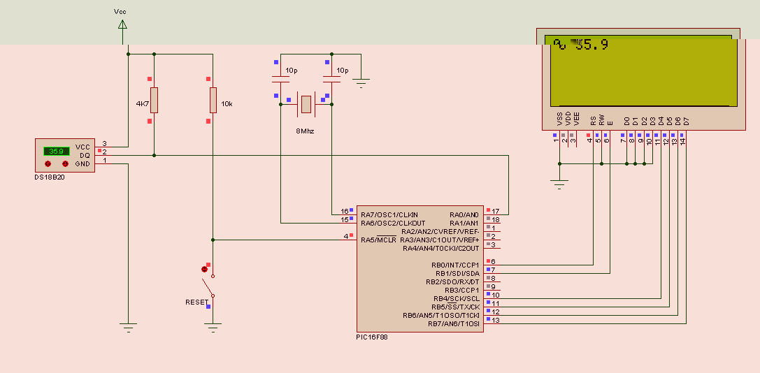
- snap0514.jpg (63.44 KiB) Viewed 15754 times
Best regards,
Eric
Re: One Wire Example - Failure on linking
Posted: Fri May 28, 2010 12:24 pm
by Jan Lichtenbelt
Dear Eric,
Thanks for the very nice hardware scheme. The only difference is that you powered the DS18B20 directly with Vcc. I connected the Vcc of the DS18B20 to the GND, meaning that this IC will be powered by means of the DQ line.
I tried your (3-wire) setup, and now it works!!! Still leaving the question why the 2-wire setup does not work (see attechment)? It returns the value 85 C, which is the power-on reset value of the temperature register of the DS18B20
(see datasheet:
http://datasheets.maxim-ic.com/en/ds/DS18S20.pdf ).
Remark: I did not installed the MOSFET, which can be the reason of the fault. It is not clear for me how to activate this MOSFET by the PIC.
I found a possible solution: Replace the pull up resistance by 1k8 instead of 4k7 and one do not need the MOSFET.
(ref:
http://www.embeddedrelated.com/groups/b ... w/6820.php)
Added later: I'm sorry, but it did not work afterall with my hard- and software. I still get the default temperature reading of 85.0 C.
Re: One Wire Example - Failure on linking
Posted: Sat May 29, 2010 10:21 am
by Eric
Hello Jan,
I am glad you have results now.
I never tried the 2-wire setup. After all, I am using standard UTP cable, where I have plenty of wires.
But I think that if you want to use the 2-wire setup, you need an extra Port to generate a hard pull-up via the mosfet during the temperature conversion stage.
A simple resistor pull-up will not do the job, hence your 85° readout.
I am not sure the Flowcode routines are build that way that they provide provision for a hard pull-up.
Maybe Ben can confirm this?
Best regards,
Eric
Re: One Wire Example - Failure on linking
Posted: Sat May 29, 2010 11:25 am
by Jan Lichtenbelt
Dallas semiconductor descibes:
"The 1-Wire bus must be switched to the strong pullup within 10μs (max) after a Convert T [44h] or Copy Scratchpad [48h] command is issued, and the bus must be held high by the pullup for the duration of the conversion (tCONV) or data transfer (tWR = 10ms). No other activity can take place on the 1-Wire bus while the pullup is enabled."
That means that in the flowcode an additional output of the PIC must switch in the time frame as given above, to control the MOSFET. I would try it, but I do not have the detailed knowledge of MOSFET's (which to be used and resistors for the gate?)
Re: One Wire Example - Failure on linking
Posted: Tue Jun 01, 2010 10:23 am
by Albert38
I would output High on the pin the one wire device is connected to instead of making it float and pulled p by the resistor. I really don't know if this works the same as making it High with the mosfet but it sound to me as working the same. Remember to disable the output on this pin before trying to send new data over the line.
Re: One Wire Example - Failure on linking
Posted: Thu Jun 10, 2010 3:08 pm
by Jan Lichtenbelt
Dear Albert,
It works now with the following hard- and software:
1) Hardware:
The DS18S20 and DS18B20 needs one I/O port for data communication. The 1-wire setup requires both GND and V+ of the DS18X20 to be connected to ground. The 1-wire needs always a pull-up resistance of 4k7 to V+. In this setup a p-MOSFET, like eg. IRF9630 was used with the S(ource) conencted to V+(max 5Volt), the D(rain) conencted to the 1-wire DQ and the G(ate) directly connected to one additional port of the microcontroller (I used port A1, see software). Additionally a 1M resistance between gate and V+ is used to decativate de MOSFET, but perhaps not necessary.
Futher hardware: E-boards EB006 and LCD EB005 with PIC16F88.
2) Software
The software needs the p-MOSFET to be activated for a special time span, between 10 usec and 750 msec (can be shorter only for DS18B20 in special cases, see tCONVERT in datasheet)
2a) Flowcode changes:
Deactivate the MOSFET directly and the beginning of program (PortA1 high)
2b) C-code changes:
Change the C-Code of the component macro 00_tx_byte of the 1-wire into: See attachment
Remark:
a) This works only for port A1 connected to the gate of the p_MOSFET. If you use an other port, you should change this C-code in agreement.
b) In flowcode manage the PortA1 after DS_1820_Start_conversion, does not work, because it is to late, because this macro waits to long ( up to 1 sec), while the MOSFET must be activated within 10 usec, after sending the data byte.
c) It works now up to 2 sensors on the 1-wire bus. With 3 sensors I get for all 3 sensors the default tempearture value of 85 C. I''m still puzzling why. Does someone has an idea? (Now 2 sensors works correctly and the third is still not working=85 C ????)
Re: One Wire Example - Failure on linking
Posted: Fri Jun 11, 2010 1:42 pm
by Jan Lichtenbelt
With some help of the forum of
http://www.elektor.com, I found that I used a relative large p-MOSFET *), which can cause additional delay's. With this knowledge, I delete the 5 usec delay in de C-code of de macro oo-tx_byte, to start the p-MOSFET. Now it works fine, even with 4 sensors.
*) Note: I used p-MOSFET IRF9630 (2A) but advised is to use BS250 (250 mA). I will try it and keep you informed.
*) Note added July 7th 2010: It works perfectly with the IRF9630. But I get error messages when using the BS250. I do not know why?
One wire: DS-temperature to floating point
Posted: Tue Jun 29, 2010 12:00 pm
by Jan Lichtenbelt
Please find a simple flowcode for converting DS18X20 temperature into floating point and into LCD visualisation of the temperature. It is not new, but perhaps it can helps somebody. With improved version June 30, 2010
One Wire - Failure on 8MHz
Posted: Mon Jul 05, 2010 5:35 pm
by Jan Lichtenbelt
I want to change the oscillator from external 19.6608 MHz to internal 8 MHz. With the external crystal the 1-wire bus is working correctly, but changing to the internal oscillator, the error message "bus error" follows.
Can someone help:
1) is it possible to use the 1-wire with the internal oscillator of PIC16F88?
2) If yes, what should I improve to prevent the bus error message (other then deleting the LCD commands)?
Jan Lichtenbelt
Re: One Wire Example - Failure on linking
Posted: Mon Jul 05, 2010 9:11 pm
by Benj
Hello Jan,
Are you sure the internal osc is running at 8MHz. Are you using the line of C code to configure the oscillator configuration register correctly?
If the hardware clock speed does not match the flowcode project clock speed then delay timings will be off and this will mean that bit banged busses such as 1 wire will have problems.
You can confirm with the 1 second flasher technique.
If the clock speed is correct and still not working then let me know and we can try to start tweaking some values.
Re: One Wire Example - Failure on linking
Posted: Wed Jul 07, 2010 9:14 am
by Jan Lichtenbelt
Dear Ben,
The C-code added is osccon= 0x70; for a 8 MHz internal oscillator. I checked your advice of a 1 sec flasher and found that the blinker is correctly blinking with the external crystal, but about 4 times slower with the internal oscillator. What did I forget?
Jan