Creating a Simple Binary Clock with the USB Project Board
Earlier in the year we attended a fair few exhibitions and shows throughout the world to exhibit our products. Back then Flowcode SE was very much in development, and we were out demonstrating the software and hardware to potential new customers. For the shows we developed several examples to demonstrate the capabilities of the software and hardware particularly relevant to Design & Technology projects at the Key Stage 4 level within the UK educational system. One of the examples we created was a simple binary clock, designed to tell the time on a series of LEDs only.
We developed this as it suited the ‘typical’ D&T project criteria, that is, to design and make a system based on an electronic system. This article provides a summary of the design process for the binary clock, what steps were performed and shows the end product example.
In D&T, students are encouraged to design and make a product. This means that the electronics behind the product may be simpler than those expected in Computer Science as there is much more than just the electronics to consider. Students will typically have to make a case for their product, considering the design process of this case, whether materials used are sustainable and green, and if not the impact they may have on the environment. They must also consider production costs. A case with marginal material costs, but large production costs would be far from ideal. We don’t quite have those constraints with our example project, but we wanted to try develop a nice simple application that demonstrated what was possible within a school using equipment likely available, within the Flowcode software, and one where we could marry up design and simulation software with hardware.
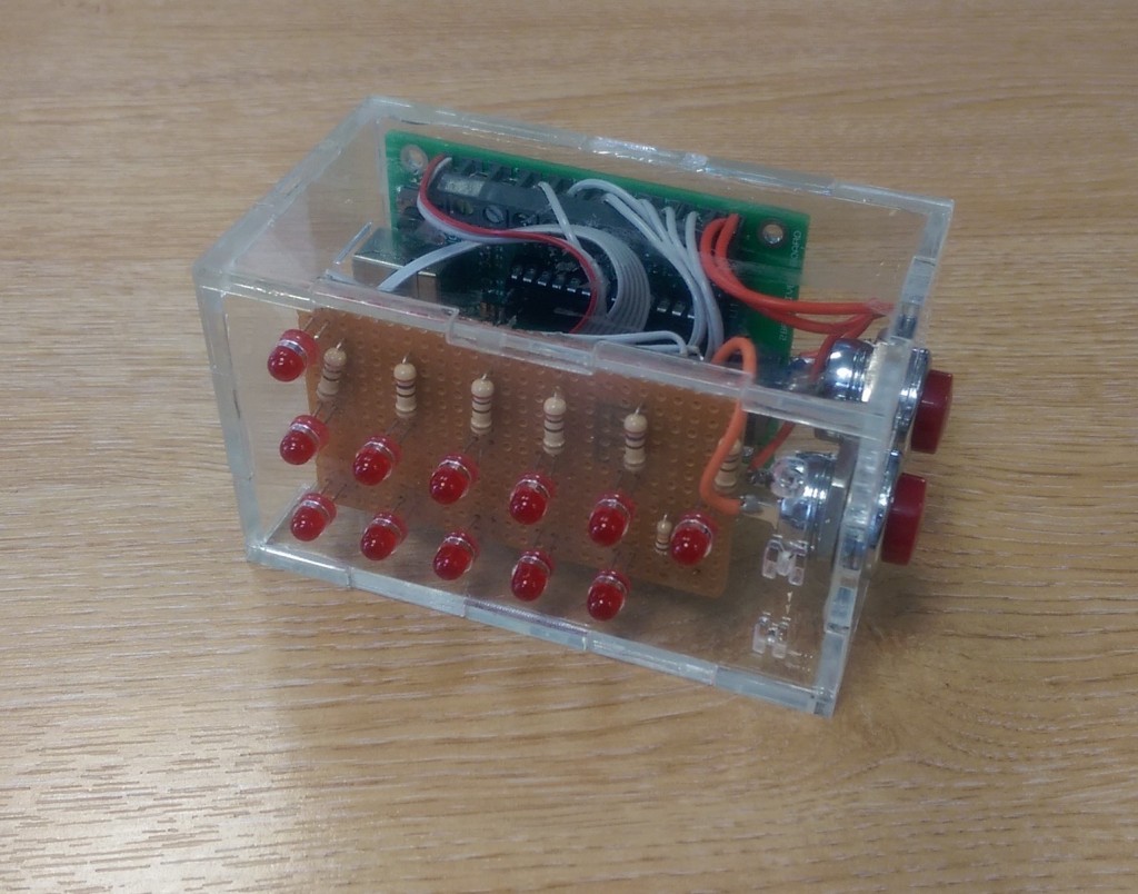
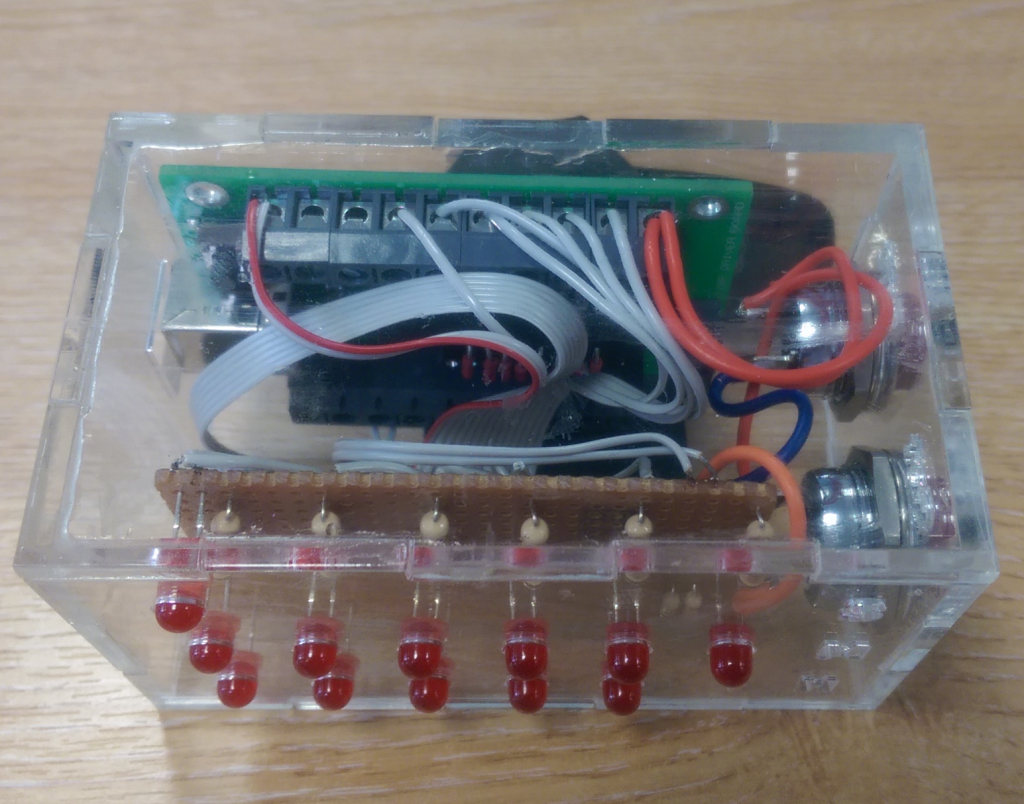
In our binary clock we utilised 3mm clear acrylic to create an outer case in which we would mount our clock LEDs and set time switches. The case was designed in SolidWorks, and exported to our laser cutter. The SolidWorks files were also imported into Flowcode to allow us to confirm the fitment of the device with our LEDs used in the clock.
With the case designed we began to design the electronics. We used the project board as mentioned, as our device was to be portable and breadboard is far from ideal in this situation as wires may come loose from the breadboard. The LED clock utilises 12 LEDs, as seen from the images it uses one LED for seconds, six for displaying the minutes and five for displaying the hours. The design also features two switches, allowing the user to set the time.
The program created is very simple in nature. It features a 1 second delay, and after that delay a variable is increased to calculate seconds. A very simple algorithm is then used to increment minutes each time seconds reaches 60 and so forth until we have achieved a clock.
The accuracy of the clock is inherently flawed as we rely on this 1 second delay being exactly a second, and also we do not consider the execution time of our algorithm used to create the hours, minutes and seconds. However, it does provide a very simple method of creating a clock. If we were to improve our design we could utilise timer interrupts to increment our count variable at exactly 1 second intervals. Also, our hardware board does not currently use a crystal oscillator, but instead relies on the internal RC network, so is inaccurate. These potential improvements would all be excellent methods of students improving their projects to improve their grades.
If you would like more information regarding Flowcode SE or the new hardware boards available please visit our website here.
![]()


