USB Project Board
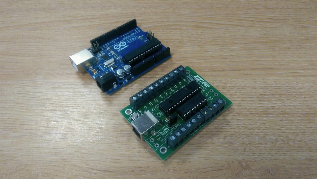
In this article we discuss the use of the Project Board to power a stepper motor. In a previous article, here, we discussed how we could use the Prototype board to enable rapid testing of a stepper motors operation. We also used four LEDs to visually observe the stepping pattern of the motor. While the breadboard is a suitable platform for rapid prototyping, it is not well suited to permanent applications, and this is where the Project board comes into play with solder terminals available for all the GPIO available on the microcontroller. These terminals are also conveniently placed at 5mm pitch, making it possible to solder screw terminals for semi-permanent applications. As seen from the image below, the Project board is almost identical in size to the Arduino Uno, but has the motor driver chip already installed in the board, making it a very cost effective product, and removing the requirement for a shield to be purchased.
Those astute readers of the previous article may also have noticed that we were operating the stepper motor directly from the outputs of the microcontroller, which only provide minimal power output. Again, another strength of the Project board here emerges, that is the inclusion of a ULN2803A driver chip, capable of providing much larger current outputs suited to motor based applications.
In this article we will demonstrate how to connect the stepper motor to the project board to increase the torque of the motor due to the extra current available. We will not require the use of status LEDs this time since we verified the operation of the stepper motor in the previous article using the Prototype board.
The buffered outputs from the driver chip are connected to PORTB of the microcontroller, and are labelled as M0-7. All other GPIO on the Project board is not buffered, but is instead connected directly to the microcontroller pins.
Having 8 buffered outputs means we can theoretically power two 4-phase stepper motors from our microcontroller, however, in this example we will only power one motor. Due to working in the development team we have already soldered screw terminals onto the Project board outputs as we are constantly designing example circuits, but if you desire you can leave the board with no screw terminals and solder the motor connections into place to make the design more permanent.
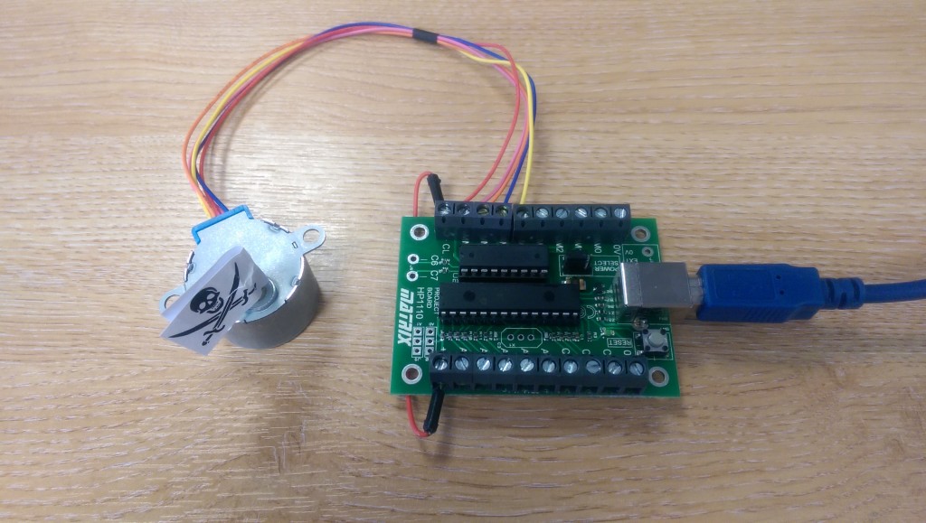
We have connected the motor to the exact same microcontroller outputs as we did with the Prototype board, that is, PORTB 4-7. The driver chip also requires power and here we simply use the same 5V supply which powers the microcontroller itself, however, you can even use an external supply if needs be to utilise a different voltage from the microcontroller or for a supply with a larger current output. We power the driver chip by connecting the terminal ‘+V’ to ‘CL’.
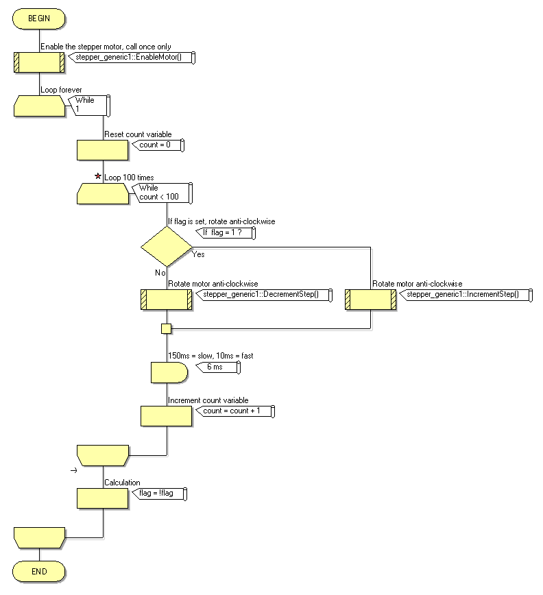
The flowchart used to power the motor is included used here also and demonstrates how we have slightly increased the complexity of the program to cause the motor to spin in a clockwise direction for a set number of steps followed by the opposite direction for the same number of steps. We have also changed the target device in the Project Explorer to that of the Project board rather than the Prototype board, however, both boards feature an identical pinout, so there is no need to change configuration bits.
Powering the stepper motor from the Project board provides a rotational force with a much greater torque, due to the extra current sourcing capabilities of the buffer chip. The final design in hardware can be seen in the image below.
In future blog articles we will look at creating some other examples with the Project board, particularly relevant to the Flowcode SE audience. For more information relating to the Project board, see here.
![]()


