|
|
| (9 intermediate revisions by 2 users not shown) |
| Line 17: |
Line 17: |
| ==Component Source Code== | | ==Component Source Code== |
|
| |
|
| Please click here to download the component source project: [https://www.flowcode.co.uk/wikicopy/componentsource/FC_Comp_Source_I2C_Master.fcfx FC_Comp_Source_I2C_Master.fcfx] | | Please click here to download the component source project: [https://www.flowcode.co.uk/wiki/componentsource/FC_Comp_Source_I2C_Master.fcfx FC_Comp_Source_I2C_Master.fcfx] |
|
| |
|
| Please click here to view the component source code (Beta): [https://www.flowcode.co.uk/FlowchartView/?wfile=componentsource/FC_Comp_Source_I2C_Master.fcfx FC_Comp_Source_I2C_Master.fcfx] | | Please click here to view the component source code (Beta): [https://www.flowcode.co.uk/FlowchartView/?wfile=componentsource/FC_Comp_Source_I2C_Master.fcfx FC_Comp_Source_I2C_Master.fcfx] |
|
| |
|
| ==Detailed description== | | ==Detailed description== |
| | |
| | |
| | |
| | |
|
| |
|
|
| |
|
| Line 108: |
Line 112: |
|
| |
|
|
| |
|
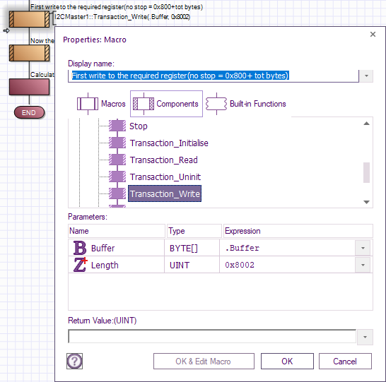
| | Referring to the Transaction_Write macro. |
| | To do a restart without a stop, instead of using just the number of bytes within the Length parameter, use 0x800 + total number of bytes to read. |
|
| |
|
| | In the I2CEEPROM.fcfx example as 2 bytes require reading with just a restart then instead of the length of 2, a length of 0x8002 is used. |
| | |
| | [[File:I2CTransaction_Write_No_Stop.png]] |
| | |
| | ==Examples== |
|
| |
|
|
| |
|
|
| |
|
|
| |
|
| ==Examples==
| |
|
| |
|
|
| |
|
| Line 155: |
Line 165: |
| ===I2C Address Scanner=== | | ===I2C Address Scanner=== |
|
| |
|
| An I2C addresses can be determined by using an {{Fcfile|IC2_Address_Sniffer_v3.fcfx|IC2 Address Sniffer}} | | An I2C addresses can be determined by using an {{Fcfile|IC2_Address_Scanner.fcfx|IC2 Address Scanner}} |
|
| |
|
| The I2C address to use is the one within the first set of square brackets. | | The I2C address to use is the one within the first set of square brackets. |
| Line 169: |
Line 179: |
| The sniffer will send data to your PC via UART to USB which can be read using serial terminal software. | | The sniffer will send data to your PC via UART to USB which can be read using serial terminal software. |
|
| |
|
| ==Macro reference==
| |
|
| |
|
| {| class="wikitable" style="width:60%; background-color:#FFFFFF;"
| |
| |-
| |
| | width="10%" align="center" style="background-color:#D8C9D8;" align="center" | [[File:Fc9-comp-macro.png]]
| |
| | width="90%" style="background-color:#D8C9D8; color:#4B008D;" | '''ReceiveByte'''
| |
| |-
| |
| | colspan="2" | Receives a byte from the I²C bus.
| |
| |-
| |
| |-
| |
| | width="10%" align="center" | [[File:Fc9-u8-icon.png]] - BYTE
| |
| | width="90%" | Last
| |
| |-
| |
| | colspan="2" | Used to signify the last byte when streaming incoming data. 0=Not last byte, 1=Last Byte
| |
| |-
| |
| | width="10%" align="center" style="border-top: 2px solid #000;" | [[File:Fc9-u8-icon.png]] - BYTE
| |
| | width="90%" style="border-top: 2px solid #000;" | ''Return''
| |
| |}
| |
|
| |
|
| | ==Macro reference== |
|
| |
|
| | ===GenericReadRegister=== |
| {| class="wikitable" style="width:60%; background-color:#FFFFFF;" | | {| class="wikitable" style="width:60%; background-color:#FFFFFF;" |
| |- | | |- |
| | width="10%" align="center" style="background-color:#D8C9D8;" align="center" | [[File:Fc9-comp-macro.png]] | | | width="10%" align="center" style="background-color:#D8C9D8;" align="center" | [[File:Fc9-comp-macro.png]] |
| | width="90%" style="background-color:#D8C9D8; color:#4B008D;" | '''Restart''' | | | width="90%" style="background-color:#D8C9D8; color:#4B008D;" | '''GenericReadRegister''' |
| |- | | |- |
| | colspan="2" | Outputs a restart condition onto the I²C bus. | | | colspan="2" | Function to perform a generic I2C read. The 7-bit device ID is automatically shifted up by one bit to make room for the read/write bit. Returns the data from the location specified. |
| |-
| |
| |-
| |
| | width="10%" align="center" style="border-top: 2px solid #000;" | [[File:Fc9-void-icon.png]] - VOID
| |
| | width="90%" style="border-top: 2px solid #000;" | ''Return''
| |
| |}
| |
| | |
| | |
| {| class="wikitable" style="width:60%; background-color:#FFFFFF;"
| |
| |-
| |
| | width="10%" align="center" style="background-color:#D8C9D8;" align="center" | [[File:Fc9-comp-macro.png]]
| |
| | width="90%" style="background-color:#D8C9D8; color:#4B008D;" | '''Stop'''
| |
| |-
| |
| | colspan="2" | Outputs a stop condition onto the I²C bus.
| |
| |-
| |
| |-
| |
| | width="10%" align="center" style="border-top: 2px solid #000;" | [[File:Fc9-void-icon.png]] - VOID
| |
| | width="90%" style="border-top: 2px solid #000;" | ''Return''
| |
| |}
| |
| | |
| | |
| {| class="wikitable" style="width:60%; background-color:#FFFFFF;"
| |
| |-
| |
| | width="10%" align="center" style="background-color:#D8C9D8;" align="center" | [[File:Fc9-comp-macro.png]]
| |
| | width="90%" style="background-color:#D8C9D8; color:#4B008D;" | '''Transaction_Write'''
| |
| |-
| |
| | colspan="2" | Attempt to write Length number of bytes to the I2C slave from the given Buffer. Ensure that the Buffer is large enough. Returns the number of bytes written, the caller should check that this matches requested Length
| |
| |- | | |- |
| |- | | |- |
| | width="10%" align="center" | [[File:Fc9-u8-icon.png]] - BYTE | | | width="10%" align="center" | [[File:Fc9-u8-icon.png]] - BYTE |
| | width="90%" | Buffer | | | width="90%" | Device_ID |
| |- | | |- |
| | colspan="2" | Buffer of bytes to write to the I2C | | | colspan="2" | 7-bit Device Address ID |
| |- | | |- |
| | width="10%" align="center" | [[File:Fc9-u16-icon.png]] - UINT | | | width="10%" align="center" | [[File:Fc9-u16-icon.png]] - UINT |
| | width="90%" | Length | | | width="90%" | Address |
| |-
| |
| | colspan="2" | Number of bytes to send out, MS bit 0x8000 signifies no Stop if set
| |
| |-
| |
| | width="10%" align="center" style="border-top: 2px solid #000;" | [[File:Fc9-u16-icon.png]] - UINT
| |
| | width="90%" style="border-top: 2px solid #000;" | ''Return''
| |
| |}
| |
| | |
| | |
| {| class="wikitable" style="width:60%; background-color:#FFFFFF;"
| |
| |-
| |
| | width="10%" align="center" style="background-color:#D8C9D8;" align="center" | [[File:Fc9-comp-macro.png]]
| |
| | width="90%" style="background-color:#D8C9D8; color:#4B008D;" | '''TransmitByte'''
| |
| |-
| |
| | colspan="2" | Sends a byte on the I²C bus. Returns the acknowledge if any. 0 represents that data was acknowledged and 1 represents no acknowledge was detected.
| |
| |- | | |- |
| | | colspan="2" | |
| |- | | |- |
| | width="10%" align="center" | [[File:Fc9-u8-icon.png]] - BYTE | | | width="10%" align="center" | [[File:Fc9-u8-icon.png]] - BYTE |
| | width="90%" | Data | | | width="90%" | AddressByteCount |
| |- | | |- |
| | colspan="2" | Data byte to send on the I²C bus. | | | colspan="2" | Specifies the number of address bytes, Range: 1 or 2 |
| |- | | |- |
| | width="10%" align="center" style="border-top: 2px solid #000;" | [[File:Fc9-u8-icon.png]] - BYTE | | | width="10%" align="center" style="border-top: 2px solid #000;" | [[File:Fc9-u8-icon.png]] - BYTE |
| Line 256: |
Line 212: |
|
| |
|
|
| |
|
| | ===GenericWriteRegister=== |
| {| class="wikitable" style="width:60%; background-color:#FFFFFF;" | | {| class="wikitable" style="width:60%; background-color:#FFFFFF;" |
| |- | | |- |
| Line 289: |
Line 246: |
|
| |
|
|
| |
|
| {| class="wikitable" style="width:60%; background-color:#FFFFFF;"
| | ===Initialise=== |
| |-
| |
| | width="10%" align="center" style="background-color:#D8C9D8;" align="center" | [[File:Fc9-comp-macro.png]]
| |
| | width="90%" style="background-color:#D8C9D8; color:#4B008D;" | '''Transaction_Uninit'''
| |
| |-
| |
| | colspan="2" | Uninitialise the I2C interface
| |
| |-
| |
| |-
| |
| | width="10%" align="center" style="border-top: 2px solid #000;" | [[File:Fc9-void-icon.png]] - VOID
| |
| | width="90%" style="border-top: 2px solid #000;" | ''Return''
| |
| |}
| |
| | |
| | |
| {| class="wikitable" style="width:60%; background-color:#FFFFFF;"
| |
| |-
| |
| | width="10%" align="center" style="background-color:#D8C9D8;" align="center" | [[File:Fc9-comp-macro.png]]
| |
| | width="90%" style="background-color:#D8C9D8; color:#4B008D;" | '''GenericReadRegister'''
| |
| |-
| |
| | colspan="2" | Function to perform a generic I2C read. The 7-bit device ID is automatically shifted up by one bit to make room for the read/write bit. Returns the data from the location specified.
| |
| |-
| |
| |-
| |
| | width="10%" align="center" | [[File:Fc9-u8-icon.png]] - BYTE
| |
| | width="90%" | Device_ID
| |
| |-
| |
| | colspan="2" | 7-bit Device Address ID
| |
| |-
| |
| | width="10%" align="center" | [[File:Fc9-u16-icon.png]] - UINT
| |
| | width="90%" | Address
| |
| |-
| |
| | colspan="2" |
| |
| |-
| |
| | width="10%" align="center" | [[File:Fc9-u8-icon.png]] - BYTE
| |
| | width="90%" | AddressByteCount
| |
| |-
| |
| | colspan="2" | Specifies the number of address bytes, Range: 1 or 2
| |
| |-
| |
| | width="10%" align="center" style="border-top: 2px solid #000;" | [[File:Fc9-u8-icon.png]] - BYTE
| |
| | width="90%" style="border-top: 2px solid #000;" | ''Return''
| |
| |}
| |
| | |
| | |
| {| class="wikitable" style="width:60%; background-color:#FFFFFF;"
| |
| |-
| |
| | width="10%" align="center" style="background-color:#D8C9D8;" align="center" | [[File:Fc9-comp-macro.png]]
| |
| | width="90%" style="background-color:#D8C9D8; color:#4B008D;" | '''Transaction_Read'''
| |
| |-
| |
| | colspan="2" | Attempt to read Length number of bytes from the I2C slave to the given Buffer. Ensure that the Buffer is large enough. Returns number of bytes read, caller should check that this matches requested Length
| |
| |-
| |
| |-
| |
| | width="10%" align="center" | [[File:Fc9-u8-icon.png]] - BYTE
| |
| | width="90%" | Buffer
| |
| |-
| |
| | colspan="2" | Buffer to store the incoming byte data
| |
| |-
| |
| | width="10%" align="center" | [[File:Fc9-u16-icon.png]] - UINT
| |
| | width="90%" | Length
| |
| |-
| |
| | colspan="2" | Number of bytes to read
| |
| |-
| |
| | width="10%" align="center" style="border-top: 2px solid #000;" | [[File:Fc9-u16-icon.png]] - UINT
| |
| | width="90%" style="border-top: 2px solid #000;" | ''Return''
| |
| |}
| |
| | |
| | |
| {| class="wikitable" style="width:60%; background-color:#FFFFFF;"
| |
| |-
| |
| | width="10%" align="center" style="background-color:#D8C9D8;" align="center" | [[File:Fc9-comp-macro.png]]
| |
| | width="90%" style="background-color:#D8C9D8; color:#4B008D;" | '''Start'''
| |
| |-
| |
| | colspan="2" | Outputs a start condition onto the I²C bus.
| |
| |-
| |
| |-
| |
| | width="10%" align="center" style="border-top: 2px solid #000;" | [[File:Fc9-void-icon.png]] - VOID
| |
| | width="90%" style="border-top: 2px solid #000;" | ''Return''
| |
| |}
| |
| | |
| | |
| {| class="wikitable" style="width:60%; background-color:#FFFFFF;"
| |
| |-
| |
| | width="10%" align="center" style="background-color:#D8C9D8;" align="center" | [[File:Fc9-comp-macro.png]]
| |
| | width="90%" style="background-color:#D8C9D8; color:#4B008D;" | '''Transaction_Initialise'''
| |
| |-
| |
| | colspan="2" | Initialise the I2C interface to communicate with a Slave device at Address Returns 0 on fail, 1 on success
| |
| |-
| |
| |-
| |
| | width="10%" align="center" | [[File:Fc9-u8-icon.png]] - BYTE
| |
| | width="90%" | Address
| |
| |-
| |
| | colspan="2" | 7-bit I2C Address without the shift for the R/W bit
| |
| |-
| |
| | width="10%" align="center" style="border-top: 2px solid #000;" | [[File:Fc9-u8-icon.png]] - BYTE
| |
| | width="90%" style="border-top: 2px solid #000;" | ''Return''
| |
| |}
| |
| | |
| | |
| {| class="wikitable" style="width:60%; background-color:#FFFFFF;" | | {| class="wikitable" style="width:60%; background-color:#FFFFFF;" |
| |- | | |- |
| Line 397: |
Line 260: |
|
| |
|
|
| |
|
| | | ===ReceiveByte=== |
| | |
| ==Property reference== | |
| | |
| {| class="wikitable" style="width:60%; background-color:#FFFFFF;"
| |
| |-
| |
| | width="10%" align="center" style="background-color:#D8C9D8;" | [[File:Fc9-prop-icon.png]]
| |
| | width="90%" style="background-color:#D8C9D8; color:#4B008D;" | '''Properties'''
| |
| |-
| |
| |-
| |
| | width="10%" align="center" style="background-color:#EAE1EA;" | [[File:Fc9-conn-icon.png]]
| |
| | width="90%" style="background-color:#EAE1EA; color:#4B008D;" | Bus Settings
| |
| |-
| |
| |-
| |
| | width="10%" align="center" | [[File:Fc9-type-16-icon.png]]
| |
| | width="90%" | Channel
| |
| |-
| |
| | colspan="2" | Channel selection
| |
| |-
| |
| | width="10%" align="center" | [[File:Fc9-type-16-icon.png]]
| |
| | width="90%" | Baud Select
| |
| |-
| |
| | colspan="2" | Baud rate option selector
| |
| |-
| |
| | width="10%" align="center" | [[File:Fc9-type-14-icon.png]]
| |
| | width="90%" | Baud Rate
| |
| |-
| |
| | colspan="2" | Baud rate to be used
| |
| |-
| |
| | width="10%" align="center" | [[File:Fc9-type-7-icon.png]]
| |
| | width="90%" | Stop Delay
| |
| |-
| |
| | colspan="2" | On older microcontroller devices there is a potential for the I2C hardware channel to lock up if there is not a 10ms delay between an I2C stop event and the next I2C start event. Most modern microcontrollers will not have a problem so this property can be disabled to speed up the I2C communications.
| |
| |-
| |
| | width="10%" align="center" | [[File:Fc9-type-16-icon.png]]
| |
| | width="90%" | Slew Rate Control
| |
| |-
| |
| | colspan="2" | Slew Rate Control Enabled or Disabled
| |
| |-
| |
| | width="10%" align="center" | [[File:Fc9-type-16-icon.png]]
| |
| | width="90%" | SMBus Inputs
| |
| |-
| |
| | colspan="2" | When Enabled input logic thresholds are compliant with SMBus specification
| |
| |-
| |
| | width="10%" align="center" style="background-color:#EAE1EA;" | [[File:Fc9-conn-icon.png]]
| |
| | width="90%" style="background-color:#EAE1EA; color:#4B008D;" | Connections
| |
| |-
| |
| |-
| |
| | width="10%" align="center" | [[File:Fc9-type-5-icon.png]]
| |
| | width="90%" | SDA
| |
| |-
| |
| | colspan="2" | Pin used for SDA (data signal)
| |
| |-
| |
| | width="10%" align="center" | [[File:Fc9-type-5-icon.png]]
| |
| | width="90%" | SCL
| |
| |-
| |
| | colspan="2" | Pin used for SCL (clock signal)
| |
| |-
| |
| | width="10%" align="center" style="background-color:#EAE1EA;" | [[File:Fc9-conn-icon.png]]
| |
| | width="90%" style="background-color:#EAE1EA; color:#4B008D;" | Simulation
| |
| |-
| |
| |-
| |
| | width="10%" align="center" | [[File:Fc9-type-10-icon.png]]
| |
| | width="90%" | Label
| |
| |-
| |
| | colspan="2" | Label shown on the comms flasher on the simulation panel.
| |
| |-
| |
| | width="10%" align="center" | [[File:Fc9-type-7-icon.png]]
| |
| | width="90%" | Scope Traces
| |
| |-
| |
| | colspan="2" | Selects if the scope traces are automatically generated or not
| |
| |-
| |
| | width="10%" align="center" | [[File:Fc9-type-7-icon.png]]
| |
| | width="90%" | Console Data
| |
| |-
| |
| | colspan="2" | Selects if the console data is automatically generated or not
| |
| |-
| |
| | width="10%" align="center" | [[File:Fc9-type-16-icon.png]]
| |
| | width="90%" | API
| |
| |-
| |
| | colspan="2" |
| |
| |}==Macro reference==
| |
| | |
| {| class="wikitable" style="width:60%; background-color:#FFFFFF;" | | {| class="wikitable" style="width:60%; background-color:#FFFFFF;" |
| |- | | |- |
| Line 498: |
Line 279: |
|
| |
|
|
| |
|
| | ===Restart=== |
| {| class="wikitable" style="width:60%; background-color:#FFFFFF;" | | {| class="wikitable" style="width:60%; background-color:#FFFFFF;" |
| |- | | |- |
| Line 511: |
Line 293: |
|
| |
|
|
| |
|
| | ===Start=== |
| {| class="wikitable" style="width:60%; background-color:#FFFFFF;" | | {| class="wikitable" style="width:60%; background-color:#FFFFFF;" |
| |- | | |- |
| | width="10%" align="center" style="background-color:#D8C9D8;" align="center" | [[File:Fc9-comp-macro.png]] | | | width="10%" align="center" style="background-color:#D8C9D8;" align="center" | [[File:Fc9-comp-macro.png]] |
| | width="90%" style="background-color:#D8C9D8; color:#4B008D;" | '''Stop''' | | | width="90%" style="background-color:#D8C9D8; color:#4B008D;" | '''Start''' |
| |- | | |- |
| | colspan="2" | Outputs a stop condition onto the I²C bus. | | | colspan="2" | Outputs a start condition onto the I²C bus. |
| |- | | |- |
| |- | | |- |
| Line 524: |
Line 307: |
|
| |
|
|
| |
|
| | ===Stop=== |
| {| class="wikitable" style="width:60%; background-color:#FFFFFF;" | | {| class="wikitable" style="width:60%; background-color:#FFFFFF;" |
| |- | | |- |
| | width="10%" align="center" style="background-color:#D8C9D8;" align="center" | [[File:Fc9-comp-macro.png]] | | | width="10%" align="center" style="background-color:#D8C9D8;" align="center" | [[File:Fc9-comp-macro.png]] |
| | width="90%" style="background-color:#D8C9D8; color:#4B008D;" | '''Transaction_Write''' | | | width="90%" style="background-color:#D8C9D8; color:#4B008D;" | '''Stop''' |
| |- | | |- |
| | colspan="2" | Attempt to write Length number of bytes to the I2C slave from the given Buffer. Ensure that the Buffer is large enough. Returns the number of bytes written, the caller should check that this matches requested Length | | | colspan="2" | Outputs a stop condition onto the I²C bus. |
| |-
| |
| |-
| |
| | width="10%" align="center" | [[File:Fc9-u8-icon.png]] - BYTE
| |
| | width="90%" | Buffer
| |
| |-
| |
| | colspan="2" | Buffer of bytes to write to the I2C
| |
| |-
| |
| | width="10%" align="center" | [[File:Fc9-u16-icon.png]] - UINT
| |
| | width="90%" | Length
| |
| |-
| |
| | colspan="2" | Number of bytes to send out, MS bit 0x8000 signifies no Stop if set
| |
| |-
| |
| | width="10%" align="center" style="border-top: 2px solid #000;" | [[File:Fc9-u16-icon.png]] - UINT
| |
| | width="90%" style="border-top: 2px solid #000;" | ''Return''
| |
| |}
| |
| | |
| | |
| {| class="wikitable" style="width:60%; background-color:#FFFFFF;"
| |
| |-
| |
| | width="10%" align="center" style="background-color:#D8C9D8;" align="center" | [[File:Fc9-comp-macro.png]]
| |
| | width="90%" style="background-color:#D8C9D8; color:#4B008D;" | '''TransmitByte'''
| |
| |- | | |- |
| | colspan="2" | Sends a byte on the I²C bus. Returns the acknowledge if any. 0 represents that data was acknowledged and 1 represents no acknowledge was detected.
| |
| |-
| |
| |-
| |
| | width="10%" align="center" | [[File:Fc9-u8-icon.png]] - BYTE
| |
| | width="90%" | Data
| |
| |-
| |
| | colspan="2" | Data byte to send on the I²C bus.
| |
| |-
| |
| | width="10%" align="center" style="border-top: 2px solid #000;" | [[File:Fc9-u8-icon.png]] - BYTE
| |
| | width="90%" style="border-top: 2px solid #000;" | ''Return''
| |
| |}
| |
|
| |
|
| |
| {| class="wikitable" style="width:60%; background-color:#FFFFFF;"
| |
| |-
| |
| | width="10%" align="center" style="background-color:#D8C9D8;" align="center" | [[File:Fc9-comp-macro.png]]
| |
| | width="90%" style="background-color:#D8C9D8; color:#4B008D;" | '''GenericWriteRegister'''
| |
| |-
| |
| | colspan="2" | Function to perform a generic I2C Write transaction. The 7-bit device ID is automatically shifted up by one bit to make room for the read/write bit.
| |
| |-
| |
| |-
| |
| | width="10%" align="center" | [[File:Fc9-u8-icon.png]] - BYTE
| |
| | width="90%" | Device_ID
| |
| |-
| |
| | colspan="2" | 7-bit Device Address ID
| |
| |-
| |
| | width="10%" align="center" | [[File:Fc9-u16-icon.png]] - UINT
| |
| | width="90%" | Address
| |
| |-
| |
| | colspan="2" |
| |
| |-
| |
| | width="10%" align="center" | [[File:Fc9-u8-icon.png]] - BYTE
| |
| | width="90%" | Data
| |
| |-
| |
| | colspan="2" | Data Byte
| |
| |-
| |
| | width="10%" align="center" | [[File:Fc9-u8-icon.png]] - BYTE
| |
| | width="90%" | AddressByteCount
| |
| |-
| |
| | colspan="2" | Specifies the number of address bytes, Range: 1 or 2
| |
| |- | | |- |
| | width="10%" align="center" style="border-top: 2px solid #000;" | [[File:Fc9-void-icon.png]] - VOID | | | width="10%" align="center" style="border-top: 2px solid #000;" | [[File:Fc9-void-icon.png]] - VOID |
| Line 598: |
Line 321: |
|
| |
|
|
| |
|
| | ===Transaction_Initialise=== |
| {| class="wikitable" style="width:60%; background-color:#FFFFFF;" | | {| class="wikitable" style="width:60%; background-color:#FFFFFF;" |
| |- | | |- |
| | width="10%" align="center" style="background-color:#D8C9D8;" align="center" | [[File:Fc9-comp-macro.png]] | | | width="10%" align="center" style="background-color:#D8C9D8;" align="center" | [[File:Fc9-comp-macro.png]] |
| | width="90%" style="background-color:#D8C9D8; color:#4B008D;" | '''Transaction_Uninit''' | | | width="90%" style="background-color:#D8C9D8; color:#4B008D;" | '''Transaction_Initialise''' |
| |- | | |- |
| | colspan="2" | Uninitialise the I2C interface | | | colspan="2" | Initialise the I2C interface to communicate with a Slave device at Address Returns 0 on fail, 1 on success |
| |-
| |
| |-
| |
| | width="10%" align="center" style="border-top: 2px solid #000;" | [[File:Fc9-void-icon.png]] - VOID
| |
| | width="90%" style="border-top: 2px solid #000;" | ''Return''
| |
| |}
| |
| | |
| | |
| {| class="wikitable" style="width:60%; background-color:#FFFFFF;"
| |
| |-
| |
| | width="10%" align="center" style="background-color:#D8C9D8;" align="center" | [[File:Fc9-comp-macro.png]]
| |
| | width="90%" style="background-color:#D8C9D8; color:#4B008D;" | '''GenericReadRegister'''
| |
| |-
| |
| | colspan="2" | Function to perform a generic I2C read. The 7-bit device ID is automatically shifted up by one bit to make room for the read/write bit. Returns the data from the location specified.
| |
| |- | | |- |
| |- | | |- |
| | width="10%" align="center" | [[File:Fc9-u8-icon.png]] - BYTE | | | width="10%" align="center" | [[File:Fc9-u8-icon.png]] - BYTE |
| | width="90%" | Device_ID
| |
| |-
| |
| | colspan="2" | 7-bit Device Address ID
| |
| |-
| |
| | width="10%" align="center" | [[File:Fc9-u16-icon.png]] - UINT
| |
| | width="90%" | Address | | | width="90%" | Address |
| |- | | |- |
| | colspan="2" | | | | colspan="2" | 7-bit I2C Address without the shift for the R/W bit |
| |-
| |
| | width="10%" align="center" | [[File:Fc9-u8-icon.png]] - BYTE
| |
| | width="90%" | AddressByteCount
| |
| |-
| |
| | colspan="2" | Specifies the number of address bytes, Range: 1 or 2
| |
| |- | | |- |
| | width="10%" align="center" style="border-top: 2px solid #000;" | [[File:Fc9-u8-icon.png]] - BYTE | | | width="10%" align="center" style="border-top: 2px solid #000;" | [[File:Fc9-u8-icon.png]] - BYTE |
| Line 639: |
Line 340: |
|
| |
|
|
| |
|
| | ===Transaction_Read=== |
| {| class="wikitable" style="width:60%; background-color:#FFFFFF;" | | {| class="wikitable" style="width:60%; background-color:#FFFFFF;" |
| |- | | |- |
| Line 662: |
Line 364: |
|
| |
|
|
| |
|
| | ===Transaction_Uninit=== |
| {| class="wikitable" style="width:60%; background-color:#FFFFFF;" | | {| class="wikitable" style="width:60%; background-color:#FFFFFF;" |
| |- | | |- |
| | width="10%" align="center" style="background-color:#D8C9D8;" align="center" | [[File:Fc9-comp-macro.png]] | | | width="10%" align="center" style="background-color:#D8C9D8;" align="center" | [[File:Fc9-comp-macro.png]] |
| | width="90%" style="background-color:#D8C9D8; color:#4B008D;" | '''Start''' | | | width="90%" style="background-color:#D8C9D8; color:#4B008D;" | '''Transaction_Uninit''' |
| |- | | |- |
| | colspan="2" | Outputs a start condition onto the I²C bus. | | | colspan="2" | Uninitialise the I2C interface |
| |-
| |
| |-
| |
| | width="10%" align="center" style="border-top: 2px solid #000;" | [[File:Fc9-void-icon.png]] - VOID
| |
| | width="90%" style="border-top: 2px solid #000;" | ''Return''
| |
| |}
| |
| | |
| | |
| {| class="wikitable" style="width:60%; background-color:#FFFFFF;"
| |
| |-
| |
| | width="10%" align="center" style="background-color:#D8C9D8;" align="center" | [[File:Fc9-comp-macro.png]]
| |
| | width="90%" style="background-color:#D8C9D8; color:#4B008D;" | '''Transaction_Initialise'''
| |
| |-
| |
| | colspan="2" | Initialise the I2C interface to communicate with a Slave device at Address Returns 0 on fail, 1 on success
| |
| |-
| |
| |-
| |
| | width="10%" align="center" | [[File:Fc9-u8-icon.png]] - BYTE
| |
| | width="90%" | Address
| |
| |-
| |
| | colspan="2" | 7-bit I2C Address without the shift for the R/W bit
| |
| |-
| |
| | width="10%" align="center" style="border-top: 2px solid #000;" | [[File:Fc9-u8-icon.png]] - BYTE
| |
| | width="90%" style="border-top: 2px solid #000;" | ''Return''
| |
| |}
| |
| | |
| | |
| {| class="wikitable" style="width:60%; background-color:#FFFFFF;"
| |
| |-
| |
| | width="10%" align="center" style="background-color:#D8C9D8;" align="center" | [[File:Fc9-comp-macro.png]]
| |
| | width="90%" style="background-color:#D8C9D8; color:#4B008D;" | '''Initialise'''
| |
| |-
| |
| | colspan="2" | Enables the I²C hardware and performs some initialization. Should be called at the start of the program or at least before any of the other I²C functions are called.
| |
| |-
| |
| |-
| |
| | width="10%" align="center" style="border-top: 2px solid #000;" | [[File:Fc9-void-icon.png]] - VOID
| |
| | width="90%" style="border-top: 2px solid #000;" | ''Return''
| |
| |}
| |
| | |
| | |
| | |
| | |
| ==Property reference==
| |
| | |
| {| class="wikitable" style="width:60%; background-color:#FFFFFF;"
| |
| |-
| |
| | width="10%" align="center" style="background-color:#D8C9D8;" | [[File:Fc9-prop-icon.png]]
| |
| | width="90%" style="background-color:#D8C9D8; color:#4B008D;" | '''Properties'''
| |
| |-
| |
| |-
| |
| | width="10%" align="center" style="background-color:#EAE1EA;" | [[File:Fc9-conn-icon.png]]
| |
| | width="90%" style="background-color:#EAE1EA; color:#4B008D;" | Bus Settings
| |
| |-
| |
| |-
| |
| | width="10%" align="center" | [[File:Fc9-type-16-icon.png]]
| |
| | width="90%" | Channel
| |
| |-
| |
| | colspan="2" | Channel selection
| |
| |-
| |
| | width="10%" align="center" | [[File:Fc9-type-16-icon.png]]
| |
| | width="90%" | Baud Select
| |
| |-
| |
| | colspan="2" | Baud rate option selector
| |
| |-
| |
| | width="10%" align="center" | [[File:Fc9-type-14-icon.png]]
| |
| | width="90%" | Baud Rate
| |
| |-
| |
| | colspan="2" | Baud rate to be used
| |
| |-
| |
| | width="10%" align="center" | [[File:Fc9-type-7-icon.png]]
| |
| | width="90%" | Stop Delay
| |
| |-
| |
| | colspan="2" | On older microcontroller devices there is a potential for the I2C hardware channel to lock up if there is not a 10ms delay between an I2C stop event and the next I2C start event. Most modern microcontrollers will not have a problem so this property can be disabled to speed up the I2C communications.
| |
| |-
| |
| | width="10%" align="center" | [[File:Fc9-type-16-icon.png]]
| |
| | width="90%" | Slew Rate Control
| |
| |-
| |
| | colspan="2" | Slew Rate Control Enabled or Disabled
| |
| |-
| |
| | width="10%" align="center" | [[File:Fc9-type-16-icon.png]]
| |
| | width="90%" | SMBus Inputs
| |
| |-
| |
| | colspan="2" | When Enabled input logic thresholds are compliant with SMBus specification
| |
| |-
| |
| | width="10%" align="center" style="background-color:#EAE1EA;" | [[File:Fc9-conn-icon.png]]
| |
| | width="90%" style="background-color:#EAE1EA; color:#4B008D;" | Connections
| |
| |-
| |
| |-
| |
| | width="10%" align="center" | [[File:Fc9-type-5-icon.png]]
| |
| | width="90%" | SDA
| |
| |-
| |
| | colspan="2" | Pin used for SDA (data signal)
| |
| |-
| |
| | width="10%" align="center" | [[File:Fc9-type-5-icon.png]]
| |
| | width="90%" | SCL
| |
| |-
| |
| | colspan="2" | Pin used for SCL (clock signal)
| |
| |-
| |
| | width="10%" align="center" style="background-color:#EAE1EA;" | [[File:Fc9-conn-icon.png]]
| |
| | width="90%" style="background-color:#EAE1EA; color:#4B008D;" | Simulation
| |
| |-
| |
| |-
| |
| | width="10%" align="center" | [[File:Fc9-type-10-icon.png]]
| |
| | width="90%" | Label
| |
| |-
| |
| | colspan="2" | Label shown on the comms flasher on the simulation panel.
| |
| |-
| |
| | width="10%" align="center" | [[File:Fc9-type-7-icon.png]]
| |
| | width="90%" | Scope Traces
| |
| |-
| |
| | colspan="2" | Selects if the scope traces are automatically generated or not
| |
| |-
| |
| | width="10%" align="center" | [[File:Fc9-type-7-icon.png]]
| |
| | width="90%" | Console Data
| |
| |-
| |
| | colspan="2" | Selects if the console data is automatically generated or not
| |
| |-
| |
| | width="10%" align="center" | [[File:Fc9-type-16-icon.png]]
| |
| | width="90%" | API
| |
| |-
| |
| | colspan="2" |
| |
| |}==Macro reference==
| |
| | |
| {| class="wikitable" style="width:60%; background-color:#FFFFFF;"
| |
| |-
| |
| | width="10%" align="center" style="background-color:#D8C9D8;" align="center" | [[File:Fc9-comp-macro.png]]
| |
| | width="90%" style="background-color:#D8C9D8; color:#4B008D;" | '''ReceiveByte'''
| |
| |-
| |
| | colspan="2" | Receives a byte from the I²C bus.
| |
| |-
| |
| |-
| |
| | width="10%" align="center" | [[File:Fc9-u8-icon.png]] - BYTE
| |
| | width="90%" | Last
| |
| |-
| |
| | colspan="2" | Used to signify the last byte when streaming incoming data. 0=Not last byte, 1=Last Byte
| |
| |-
| |
| | width="10%" align="center" style="border-top: 2px solid #000;" | [[File:Fc9-u8-icon.png]] - BYTE
| |
| | width="90%" style="border-top: 2px solid #000;" | ''Return''
| |
| |}
| |
| | |
| | |
| {| class="wikitable" style="width:60%; background-color:#FFFFFF;"
| |
| |-
| |
| | width="10%" align="center" style="background-color:#D8C9D8;" align="center" | [[File:Fc9-comp-macro.png]]
| |
| | width="90%" style="background-color:#D8C9D8; color:#4B008D;" | '''Restart'''
| |
| |-
| |
| | colspan="2" | Outputs a restart condition onto the I²C bus.
| |
| |-
| |
| |-
| |
| | width="10%" align="center" style="border-top: 2px solid #000;" | [[File:Fc9-void-icon.png]] - VOID
| |
| | width="90%" style="border-top: 2px solid #000;" | ''Return''
| |
| |}
| |
| | |
| | |
| {| class="wikitable" style="width:60%; background-color:#FFFFFF;"
| |
| |-
| |
| | width="10%" align="center" style="background-color:#D8C9D8;" align="center" | [[File:Fc9-comp-macro.png]]
| |
| | width="90%" style="background-color:#D8C9D8; color:#4B008D;" | '''Stop'''
| |
| |-
| |
| | colspan="2" | Outputs a stop condition onto the I²C bus.
| |
| |- | | |- |
| |- | | |- |
| Line 833: |
Line 378: |
|
| |
|
|
| |
|
| | ===Transaction_Write=== |
| {| class="wikitable" style="width:60%; background-color:#FFFFFF;" | | {| class="wikitable" style="width:60%; background-color:#FFFFFF;" |
| |- | | |- |
| Line 856: |
Line 402: |
|
| |
|
|
| |
|
| | ===TransmitByte=== |
| {| class="wikitable" style="width:60%; background-color:#FFFFFF;" | | {| class="wikitable" style="width:60%; background-color:#FFFFFF;" |
| |- | | |- |
| Line 872: |
Line 419: |
| | width="90%" style="border-top: 2px solid #000;" | ''Return'' | | | width="90%" style="border-top: 2px solid #000;" | ''Return'' |
| |} | | |} |
|
| |
|
| |
| {| class="wikitable" style="width:60%; background-color:#FFFFFF;"
| |
| |-
| |
| | width="10%" align="center" style="background-color:#D8C9D8;" align="center" | [[File:Fc9-comp-macro.png]]
| |
| | width="90%" style="background-color:#D8C9D8; color:#4B008D;" | '''GenericWriteRegister'''
| |
| |-
| |
| | colspan="2" | Function to perform a generic I2C Write transaction. The 7-bit device ID is automatically shifted up by one bit to make room for the read/write bit.
| |
| |-
| |
| |-
| |
| | width="10%" align="center" | [[File:Fc9-u8-icon.png]] - BYTE
| |
| | width="90%" | Device_ID
| |
| |-
| |
| | colspan="2" | 7-bit Device Address ID
| |
| |-
| |
| | width="10%" align="center" | [[File:Fc9-u16-icon.png]] - UINT
| |
| | width="90%" | Address
| |
| |-
| |
| | colspan="2" |
| |
| |-
| |
| | width="10%" align="center" | [[File:Fc9-u8-icon.png]] - BYTE
| |
| | width="90%" | Data
| |
| |-
| |
| | colspan="2" | Data Byte
| |
| |-
| |
| | width="10%" align="center" | [[File:Fc9-u8-icon.png]] - BYTE
| |
| | width="90%" | AddressByteCount
| |
| |-
| |
| | colspan="2" | Specifies the number of address bytes, Range: 1 or 2
| |
| |-
| |
| | width="10%" align="center" style="border-top: 2px solid #000;" | [[File:Fc9-void-icon.png]] - VOID
| |
| | width="90%" style="border-top: 2px solid #000;" | ''Return''
| |
| |}
| |
|
| |
|
| |
| {| class="wikitable" style="width:60%; background-color:#FFFFFF;"
| |
| |-
| |
| | width="10%" align="center" style="background-color:#D8C9D8;" align="center" | [[File:Fc9-comp-macro.png]]
| |
| | width="90%" style="background-color:#D8C9D8; color:#4B008D;" | '''Transaction_Uninit'''
| |
| |-
| |
| | colspan="2" | Uninitialise the I2C interface
| |
| |-
| |
| |-
| |
| | width="10%" align="center" style="border-top: 2px solid #000;" | [[File:Fc9-void-icon.png]] - VOID
| |
| | width="90%" style="border-top: 2px solid #000;" | ''Return''
| |
| |}
| |
|
| |
|
| |
| {| class="wikitable" style="width:60%; background-color:#FFFFFF;"
| |
| |-
| |
| | width="10%" align="center" style="background-color:#D8C9D8;" align="center" | [[File:Fc9-comp-macro.png]]
| |
| | width="90%" style="background-color:#D8C9D8; color:#4B008D;" | '''GenericReadRegister'''
| |
| |-
| |
| | colspan="2" | Function to perform a generic I2C read. The 7-bit device ID is automatically shifted up by one bit to make room for the read/write bit. Returns the data from the location specified.
| |
| |-
| |
| |-
| |
| | width="10%" align="center" | [[File:Fc9-u8-icon.png]] - BYTE
| |
| | width="90%" | Device_ID
| |
| |-
| |
| | colspan="2" | 7-bit Device Address ID
| |
| |-
| |
| | width="10%" align="center" | [[File:Fc9-u16-icon.png]] - UINT
| |
| | width="90%" | Address
| |
| |-
| |
| | colspan="2" |
| |
| |-
| |
| | width="10%" align="center" | [[File:Fc9-u8-icon.png]] - BYTE
| |
| | width="90%" | AddressByteCount
| |
| |-
| |
| | colspan="2" | Specifies the number of address bytes, Range: 1 or 2
| |
| |-
| |
| | width="10%" align="center" style="border-top: 2px solid #000;" | [[File:Fc9-u8-icon.png]] - BYTE
| |
| | width="90%" style="border-top: 2px solid #000;" | ''Return''
| |
| |}
| |
|
| |
|
| |
| {| class="wikitable" style="width:60%; background-color:#FFFFFF;"
| |
| |-
| |
| | width="10%" align="center" style="background-color:#D8C9D8;" align="center" | [[File:Fc9-comp-macro.png]]
| |
| | width="90%" style="background-color:#D8C9D8; color:#4B008D;" | '''Transaction_Read'''
| |
| |-
| |
| | colspan="2" | Attempt to read Length number of bytes from the I2C slave to the given Buffer. Ensure that the Buffer is large enough. Returns number of bytes read, caller should check that this matches requested Length
| |
| |-
| |
| |-
| |
| | width="10%" align="center" | [[File:Fc9-u8-icon.png]] - BYTE
| |
| | width="90%" | Buffer
| |
| |-
| |
| | colspan="2" | Buffer to store the incoming byte data
| |
| |-
| |
| | width="10%" align="center" | [[File:Fc9-u16-icon.png]] - UINT
| |
| | width="90%" | Length
| |
| |-
| |
| | colspan="2" | Number of bytes to read
| |
| |-
| |
| | width="10%" align="center" style="border-top: 2px solid #000;" | [[File:Fc9-u16-icon.png]] - UINT
| |
| | width="90%" style="border-top: 2px solid #000;" | ''Return''
| |
| |}
| |
|
| |
|
| |
| {| class="wikitable" style="width:60%; background-color:#FFFFFF;"
| |
| |-
| |
| | width="10%" align="center" style="background-color:#D8C9D8;" align="center" | [[File:Fc9-comp-macro.png]]
| |
| | width="90%" style="background-color:#D8C9D8; color:#4B008D;" | '''Start'''
| |
| |-
| |
| | colspan="2" | Outputs a start condition onto the I²C bus.
| |
| |-
| |
| |-
| |
| | width="10%" align="center" style="border-top: 2px solid #000;" | [[File:Fc9-void-icon.png]] - VOID
| |
| | width="90%" style="border-top: 2px solid #000;" | ''Return''
| |
| |}
| |
|
| |
|
| |
| {| class="wikitable" style="width:60%; background-color:#FFFFFF;"
| |
| |-
| |
| | width="10%" align="center" style="background-color:#D8C9D8;" align="center" | [[File:Fc9-comp-macro.png]]
| |
| | width="90%" style="background-color:#D8C9D8; color:#4B008D;" | '''Transaction_Initialise'''
| |
| |-
| |
| | colspan="2" | Initialise the I2C interface to communicate with a Slave device at Address Returns 0 on fail, 1 on success
| |
| |-
| |
| |-
| |
| | width="10%" align="center" | [[File:Fc9-u8-icon.png]] - BYTE
| |
| | width="90%" | Address
| |
| |-
| |
| | colspan="2" | 7-bit I2C Address without the shift for the R/W bit
| |
| |-
| |
| | width="10%" align="center" style="border-top: 2px solid #000;" | [[File:Fc9-u8-icon.png]] - BYTE
| |
| | width="90%" style="border-top: 2px solid #000;" | ''Return''
| |
| |}
| |
|
| |
|
| |
| {| class="wikitable" style="width:60%; background-color:#FFFFFF;"
| |
| |-
| |
| | width="10%" align="center" style="background-color:#D8C9D8;" align="center" | [[File:Fc9-comp-macro.png]]
| |
| | width="90%" style="background-color:#D8C9D8; color:#4B008D;" | '''Initialise'''
| |
| |-
| |
| | colspan="2" | Enables the I²C hardware and performs some initialization. Should be called at the start of the program or at least before any of the other I²C functions are called.
| |
| |-
| |
| |-
| |
| | width="10%" align="center" style="border-top: 2px solid #000;" | [[File:Fc9-void-icon.png]] - VOID
| |
| | width="90%" style="border-top: 2px solid #000;" | ''Return''
| |
| |}
| |
|
| |
|
| |
|
| |
|
|
| |
|
| Author
|
Matrix Ltd.
|
| Version
|
1.4
|
| Category
|
Comms: Interface
|
I2C Master component
Generic Two Wire I2C Communications Interface
Component Source Code
Please click here to download the component source project: FC_Comp_Source_I2C_Master.fcfx
Please click here to view the component source code (Beta): FC_Comp_Source_I2C_Master.fcfx
Detailed description
Overview
The I2C bus is a medium speed communications bus which is usually best suited for talking between devices situated on the same circuit board. Due to the high frequency digital nature of the bus care should be taken to keep tracks as short as possible and as far away as possible from other sources of noise. A typical I2C bus consists of two signals, data and clock. The I2C bus usually consists of a single master device and then one or more slave devices. The master device initiates all the communications and can only communicate with a single device on the bus at a time by sending a unique device address as the first byte.
Each I2C transaction consists of a start and a stop as well as one or more data bytes made up of 8 clock cycles allowing the 8-bits of each byte to be transferred. Each byte send is followed by an Ack (acknowledged) or a Nak (not acknowledged) from the receiving device.

Pull up resistors
The I2C bus usually requires pull up resistors in the range of 4.7K to 10K between the two I2C signals and VCC. Some I2C devices have the pull up resistors built in so as to avoid external components.
The pull up resistors can be useful when interfacing a 5V microcontroller to a 3V3 sensor as the pull up resistor can be connected to 3V3 to eliminate the need for voltage level shifting.
Start / Restart / Stop
The Start, Restart and Stop operations are each states which the bus can be put into using the I2C specification.
Generic Write Transaction
A generic write transaction to a memory device might look something like this:
Start
Send External Device Address Byte (Write mode)
Send Internal Address Byte
Send Data Byte
Stop
Generic Read Transaction
A generic read transaction to a memory device might look something like this:
Start
Send External Device Address Byte (Write mode)
Send Internal Address Byte
Restart
Send External Device Address Byte (Read mode)
Read Data Byte
Stop
Referring to the Transaction_Write macro.
To do a restart without a stop, instead of using just the number of bytes within the Length parameter, use 0x800 + total number of bytes to read.
In the I2CEEPROM.fcfx example as 2 bytes require reading with just a restart then instead of the length of 2, a length of 0x8002 is used.
Examples
More information on I2C can be found here,
Matrix Flowcode Blog: Simplified communications I2C and SPI
Generic I2C EEPROM
Example file demonstrating how to read and write bytes from a generic I2C EEPROM device.
 I2CEEPROM
I2C Transaction Mode
Transaction mode can be used on all target devices.
If not using transaction mode then your code won't work on ARM or ESP.
With transaction mode, there are fewer component macros required than in Non-transaction read/write mode.
The I2CEEPROM.fcfx Example file demonstrates how I2C transaction component macros can be used to write and read to the memory registers of an I2C external EEPROM
The I2C Transaction Example file demonstrates how I2C transaction component macros can be used to write and read to the minutes register of DS1307/DS3231 RTC.
If simulation Mode within properties is set to Yes, then the minutes are read from your PC time via a dll.
You can expand using the dll to retrieve the whole date and time.
I2C Transaction Example
I2C Address Scanner
An I2C addresses can be determined by using an
IC2 Address Scanner
The I2C address to use is the one within the first set of square brackets.
For example, with my backpack display, the correct address to use is 0x3F [63]:
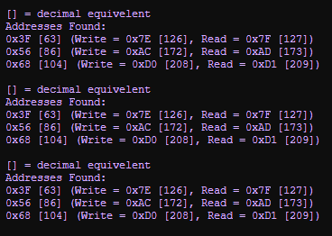
The other two Addresses i.e. 0x56 [86] and 0x68 [104] is for other connected devices, 24C32 EEPROM and DS3231 RTC respectively.
Note The I2c addresses scan will repeat every 5seconds.
The sniffer will send data to your PC via UART to USB which can be read using serial terminal software.
Macro reference
GenericReadRegister

|
GenericReadRegister
|
| Function to perform a generic I2C read. The 7-bit device ID is automatically shifted up by one bit to make room for the read/write bit. Returns the data from the location specified.
|
 - BYTE - BYTE
|
Device_ID
|
| 7-bit Device Address ID
|
 - UINT - UINT
|
Address
|
|
|
| - BYTE
|
AddressByteCount
|
| Specifies the number of address bytes, Range: 1 or 2
|
| - BYTE
|
Return
|
GenericWriteRegister
|
|
GenericWriteRegister
|
| Function to perform a generic I2C Write transaction. The 7-bit device ID is automatically shifted up by one bit to make room for the read/write bit.
|
| - BYTE
|
Device_ID
|
| 7-bit Device Address ID
|
| - UINT
|
Address
|
|
|
| - BYTE
|
Data
|
| Data Byte
|
| - BYTE
|
AddressByteCount
|
| Specifies the number of address bytes, Range: 1 or 2
|
 - VOID - VOID
|
Return
|
Initialise
|
|
Initialise
|
| Enables the I²C hardware and performs some initialization. Should be called at the start of the program or at least before any of the other I²C functions are called.
|
| - VOID
|
Return
|
ReceiveByte
|
|
ReceiveByte
|
| Receives a byte from the I²C bus.
|
| - BYTE
|
Last
|
| Used to signify the last byte when streaming incoming data. 0=Not last byte, 1=Last Byte
|
| - BYTE
|
Return
|
Restart
|
|
Restart
|
| Outputs a restart condition onto the I²C bus.
|
| - VOID
|
Return
|
Start
|
|
Start
|
| Outputs a start condition onto the I²C bus.
|
| - VOID
|
Return
|
Stop
|
|
Stop
|
| Outputs a stop condition onto the I²C bus.
|
| - VOID
|
Return
|
Transaction_Initialise
|
|
Transaction_Initialise
|
| Initialise the I2C interface to communicate with a Slave device at Address Returns 0 on fail, 1 on success
|
| - BYTE
|
Address
|
| 7-bit I2C Address without the shift for the R/W bit
|
| - BYTE
|
Return
|
Transaction_Read
|
|
Transaction_Read
|
| Attempt to read Length number of bytes from the I2C slave to the given Buffer. Ensure that the Buffer is large enough. Returns number of bytes read, caller should check that this matches requested Length
|
| - BYTE
|
Buffer
|
| Buffer to store the incoming byte data
|
| - UINT
|
Length
|
| Number of bytes to read
|
| - UINT
|
Return
|
Transaction_Uninit
|
|
Transaction_Uninit
|
| Uninitialise the I2C interface
|
| - VOID
|
Return
|
Transaction_Write
|
|
Transaction_Write
|
| Attempt to write Length number of bytes to the I2C slave from the given Buffer. Ensure that the Buffer is large enough. Returns the number of bytes written, the caller should check that this matches requested Length
|
| - BYTE
|
Buffer
|
| Buffer of bytes to write to the I2C
|
| - UINT
|
Length
|
| Number of bytes to send out, MS bit 0x8000 signifies no Stop if set
|
| - UINT
|
Return
|
TransmitByte
|
|
TransmitByte
|
| Sends a byte on the I²C bus. Returns the acknowledge if any. 0 represents that data was acknowledged and 1 represents no acknowledge was detected.
|
| - BYTE
|
Data
|
| Data byte to send on the I²C bus.
|
| - BYTE
|
Return
|
Property reference

|
Properties
|

|
Bus Settings
|

|
Channel
|
| Channel selection
|
|
|
Baud Select
|
| Baud rate option selector
|

|
Baud Rate
|
| Baud rate to be used
|

|
Stop Delay
|
| On older microcontroller devices there is a potential for the I2C hardware channel to lock up if there is not a 10ms delay between an I2C stop event and the next I2C start event. Most modern microcontrollers will not have a problem so this property can be disabled to speed up the I2C communications.
|
|
|
Slew Rate Control
|
| Slew Rate Control Enabled or Disabled
|
|
|
SMBus Inputs
|
| When Enabled input logic thresholds are compliant with SMBus specification
|
|
|
Connections
|

|
SDA
|
| Pin used for SDA (data signal)
|
|
|
SCL
|
| Pin used for SCL (clock signal)
|
|
|
Simulation
|

|
Label
|
| Label shown on the comms flasher on the simulation panel.
|
|
|
Scope Traces
|
| Selects if the scope traces are automatically generated or not
|
|
|
Console Data
|
| Selects if the console data is automatically generated or not
|
|
|
API
|
|
|


