|
|
| (16 intermediate revisions by 3 users not shown) |
| Line 16: |
Line 16: |
|
| |
|
| ==Component Source Code== | | ==Component Source Code== |
| | |
| | Please click here to download the component source project: [https://www.flowcode.co.uk/wiki/componentsource/FC_Comp_Source_LED_Array_2dgi.fcfx FC_Comp_Source_LED_Array_2dgi.fcfx] |
|
| |
|
| Please click here to view the component source code (Beta): [https://www.flowcode.co.uk/FlowchartView/?wfile=componentsource/FC_Comp_Source_LED_Array_2dgi.fcfx FC_Comp_Source_LED_Array_2dgi.fcfx] | | Please click here to view the component source code (Beta): [https://www.flowcode.co.uk/FlowchartView/?wfile=componentsource/FC_Comp_Source_LED_Array_2dgi.fcfx FC_Comp_Source_LED_Array_2dgi.fcfx] |
| Line 33: |
Line 35: |
|
| |
|
|
| |
|
| ''No detailed description exists yet for this component''
| |
|
| |
|
| ==Examples==
| |
|
| |
|
|
| |
|
| Line 41: |
Line 41: |
|
| |
|
|
| |
|
| | ''No detailed description exists yet for this component'' |
|
| |
|
| | ==Examples== |
|
| |
|
|
| |
|
| | Example program which uses the point graph macro and loops to create a knight rider effect using the LED array. |
|
| |
|
| | {{Fcfile|LED_KnightRider_2D.fcfx|LED KnightRider}} |
|
| |
|
|
| |
|
| | Example program which reads an analogue value from an analogue input voltage and displays the reading in Binary on the LED array. |
|
| |
|
| | {{Fcfile|LED_Count_2D.fcfx|LED Count}} |
|
| |
|
|
| |
|
| Each segment will require a current limiting resistor.
| | LEDs can be wired either active high or active low. The LED Array components have a property allowing you to configure which LED type your using. |
|
| |
|
| This LED Calculator tool is a good resource for calculating the correct LED series protection resistor.
| | [[File:LED_Active.jpg]] |
|
| |
|
| [https://www.digikey.co.uk/en/resources/conversion-calculators/conversion-calculator-led-series-resistor LED Resistor Calculator Tool]
| |
|
| |
|
| | An active high LED will light when the microcontroller pin is outputting a logic 1 and be off when the microcontroller pin is outputting a logic 0 or in input mode. |
|
| |
|
|
| |
|
| ===Simple Counter===
| | An active low LED will light when the microcontroller pin is outputting a logic 0 and be off when the microcontroller pin is outputting a logic 1 or in input mode. |
|
| |
|
| This example counts up from 0 to 9 on the 7-segment display before wrapping back to 0 and starting again. When displaying odd numbers we light the decimal point segment.
| |
| {{Fcfile|7Seg_Test.fcfx|7Segment Display Example}}
| |
|
| |
|
| | The series resistor can be on either side of the LED and acts to protect the LED from damage due to excess current. The value of resistor used can be changed based on the brightness of the LED and power consumption. |
|
| |
|
| ===Multiplexed Counter===
| |
|
| |
|
| This next example counts up from 0 to 99 on two 7-segment displays before wrapping back to 0 and starting again. The two displays are driven using a technique called multiplexing. A timer interrupt is used to perform the multiplexing leaving our program free to perform other tasks. Each 7-segment display shares the same segment pin connections but has a unique common pin connection to allow each individual 7-segment display to display a unique value. | | This LED Calculator tool is a good resource for calculating the correct LED series protection resistor. |
| {{Fcfile|7Seg_Test2.fcfx|7Segment Multiplex}}
| |
|
| |
|
| | | [https://www.digikey.co.uk/en/resources/conversion-calculators/conversion-calculator-led-series-resistor LED Resistor Calculator Tool] |
| ===Stop Watch===
| |
| | |
| This next example uses a timer interrupt to multiplex between the displays and a second timer interrupt to count the passing of time allowing for accurate timings. Using four single 7-seg components we create a timer capable of monitoring time from 0.0 to 999.9 seconds in multiples of 100ms. The second timer interrupt flags to the main when the count value has changed allowing the heavier calculations to extract the digits from the counter to be done outside of the high speed interrupt routine and therefore maintain accurate timing.
| |
| | |
| Switches connected to Port D allow for the timer to be started, stopped and reset.
| |
| {{Fcfile|7Seg_Test3.fcfx|7Segment Timer}}
| |
| | |
| | |
| ===Segment Control===
| |
| | |
| This example shows a method to display custom characters on 7-segment displays and also allows for numeric values to be displayed.
| |
| | |
| {{Fcfile|7segCharDemo.fcfx|7Segment Character Demo}}
| |
|
| |
|
| ==Macro reference== | | ==Macro reference== |
|
| |
|
| {| class="wikitable" style="width:60%; background-color:#FFFFFF;" | | ===AllOff=== |
| | {| class="mtx-class-macrotable wikitable" |
| |- | | |- |
| | width="10%" align="center" style="background-color:#D8C9D8;" align="center" | [[File:Fc9-comp-macro.png]] | | | width="10%" align="center" class="mtx-class-macrohead" | [[File:Fc9-comp-macro.png]] |
| | width="90%" style="background-color:#D8C9D8; color:#4B008D;" | '''BarGraph''' | | | width="90%" class="mtx-class-macrohead" | '''AllOff''' |
| |- | | |- |
| | colspan="2" | Turns on the first N elements of the array - for generating bar graph metes etc. | | | colspan="2" | Turns off all elements |
| |-
| |
| |-
| |
| | width="10%" align="center" | [[File:Fc9-u8-icon.png]] - BYTE
| |
| | width="90%" | Length
| |
| |- | | |- |
| | colspan="2" | How many items to light up.
| |
| |- | | |- |
| | width="10%" align="center" style="border-top: 2px solid #000;" | [[File:Fc9-void-icon.png]] - VOID | | | width="10%" align="center" style="border-top: 2px solid #000;" | [[File:Fc9-void-icon.png]] - VOID |
| Line 104: |
Line 90: |
|
| |
|
|
| |
|
| {| class="wikitable" style="width:60%; background-color:#FFFFFF;" | | ===AllOn=== |
| | {| class="mtx-class-macrotable wikitable" |
| |- | | |- |
| | width="10%" align="center" style="background-color:#D8C9D8;" align="center" | [[File:Fc9-comp-macro.png]] | | | width="10%" align="center" class="mtx-class-macrohead" | [[File:Fc9-comp-macro.png]] |
| | width="90%" style="background-color:#D8C9D8; color:#4B008D;" | '''LEDOn''' | | | width="90%" class="mtx-class-macrohead" | '''AllOn''' |
| |-
| |
| | colspan="2" | Turn on the selected LED.
| |
| |-
| |
| |-
| |
| | width="10%" align="center" | [[File:Fc9-u8-icon.png]] - BYTE
| |
| | width="90%" | Index
| |
| |-
| |
| | colspan="2" | Index of the LED to turn on.
| |
| |-
| |
| | width="10%" align="center" style="border-top: 2px solid #000;" | [[File:Fc9-void-icon.png]] - VOID
| |
| | width="90%" style="border-top: 2px solid #000;" | ''Return''
| |
| |}
| |
| | |
| | |
| {| class="wikitable" style="width:60%; background-color:#FFFFFF;"
| |
| |-
| |
| | width="10%" align="center" style="background-color:#D8C9D8;" align="center" | [[File:Fc9-comp-macro.png]]
| |
| | width="90%" style="background-color:#D8C9D8; color:#4B008D;" | '''AllOn'''
| |
| |- | | |- |
| | colspan="2" | Turns on all elements | | | colspan="2" | Turns on all elements |
| Line 135: |
Line 104: |
|
| |
|
|
| |
|
| {| class="wikitable" style="width:60%; background-color:#FFFFFF;"
| | ===BarGraph=== |
| |-
| | {| class="mtx-class-macrotable wikitable" |
| | width="10%" align="center" style="background-color:#D8C9D8;" align="center" | [[File:Fc9-comp-macro.png]]
| |
| | width="90%" style="background-color:#D8C9D8; color:#4B008D;" | '''LEDOff'''
| |
| |-
| |
| | colspan="2" | Turn off the selected led.
| |
| |-
| |
| |-
| |
| | width="10%" align="center" | [[File:Fc9-u8-icon.png]] - BYTE
| |
| | width="90%" | Index
| |
| |-
| |
| | colspan="2" | Index of the LED to turn on.
| |
| |-
| |
| | width="10%" align="center" style="border-top: 2px solid #000;" | [[File:Fc9-void-icon.png]] - VOID
| |
| | width="90%" style="border-top: 2px solid #000;" | ''Return''
| |
| |}
| |
| | |
| | |
| {| class="wikitable" style="width:60%; background-color:#FFFFFF;" | |
| |-
| |
| | width="10%" align="center" style="background-color:#D8C9D8;" align="center" | [[File:Fc9-comp-macro.png]]
| |
| | width="90%" style="background-color:#D8C9D8; color:#4B008D;" | '''PointGraph'''
| |
| |-
| |
| | colspan="2" | Turns on the Indexed LED and turns all others off. Does nothing if the index is out of range.
| |
| |-
| |
| |-
| |
| | width="10%" align="center" | [[File:Fc9-u8-icon.png]] - BYTE
| |
| | width="90%" | Index
| |
| |-
| |
| | colspan="2" | The LED to show.
| |
| |-
| |
| | width="10%" align="center" style="border-top: 2px solid #000;" | [[File:Fc9-void-icon.png]] - VOID
| |
| | width="90%" style="border-top: 2px solid #000;" | ''Return''
| |
| |}
| |
| | |
| | |
| {| class="wikitable" style="width:60%; background-color:#FFFFFF;"
| |
| |-
| |
| | width="10%" align="center" style="background-color:#D8C9D8;" align="center" | [[File:Fc9-comp-macro.png]]
| |
| | width="90%" style="background-color:#D8C9D8; color:#4B008D;" | '''WriteValue'''
| |
| |-
| |
| | colspan="2" | Write a number which is presented on the LEDs in binary.
| |
| |-
| |
| |-
| |
| | width="10%" align="center" | [[File:Fc9-u8-icon.png]] - BYTE
| |
| | width="90%" | Value
| |
| |-
| |
| | colspan="2" | Provide a value to be written to the LEDs in binary
| |
| |-
| |
| | width="10%" align="center" style="border-top: 2px solid #000;" | [[File:Fc9-void-icon.png]] - VOID
| |
| | width="90%" style="border-top: 2px solid #000;" | ''Return''
| |
| |}
| |
| | |
| | |
| {| class="wikitable" style="width:60%; background-color:#FFFFFF;"
| |
| |-
| |
| | width="10%" align="center" style="background-color:#D8C9D8;" align="center" | [[File:Fc9-comp-macro.png]]
| |
| | width="90%" style="background-color:#D8C9D8; color:#4B008D;" | '''AllOff'''
| |
| |-
| |
| | colspan="2" | Turns off all elements
| |
| |-
| |
| |-
| |
| | width="10%" align="center" style="border-top: 2px solid #000;" | [[File:Fc9-void-icon.png]] - VOID
| |
| | width="90%" style="border-top: 2px solid #000;" | ''Return''
| |
| |}
| |
| | |
| | |
| | |
| | |
| ==Property reference==
| |
| | |
| {| class="wikitable" style="width:60%; background-color:#FFFFFF;"
| |
| |-
| |
| | width="10%" align="center" style="background-color:#D8C9D8;" | [[File:Fc9-prop-icon.png]]
| |
| | width="90%" style="background-color:#D8C9D8; color:#4B008D;" | '''Properties'''
| |
| |-
| |
| |-
| |
| | width="10%" align="center" | [[File:Fc9-type-16-icon.png]]
| |
| | width="90%" | Count
| |
| |-
| |
| | colspan="2" | The number of LEDs in the array from 1 to 8.
| |
| |-
| |
| | width="10%" align="center" style="background-color:#EAE1EA;" | [[File:Fc9-conn-icon.png]]
| |
| | width="90%" style="background-color:#EAE1EA; color:#4B008D;" | Connections
| |
| |-
| |
| |-
| |
| | width="10%" align="center" | [[File:Fc9-type-16-icon.png]]
| |
| | width="90%" | Output Mode
| |
| |-
| |
| | colspan="2" |
| |
| |-
| |
| | width="10%" align="center" | [[File:Fc9-type-19-icon.png]]
| |
| | width="90%" | Port
| |
| |-
| |
| | colspan="2" |
| |
| |-
| |
| | width="10%" align="center" | [[File:Fc9-type-16-icon.png]]
| |
| | width="90%" | Polarity
| |
| |-
| |
| | colspan="2" |
| |
| |-
| |
| | width="10%" align="center" style="background-color:#EAE1EA;" | [[File:Fc9-conn-icon.png]]
| |
| | width="90%" style="background-color:#EAE1EA; color:#4B008D;" | Simulation
| |
| |-
| |
| |-
| |
| | width="10%" align="center" | [[File:Fc9-type-16-icon.png]]
| |
| | width="90%" | Switch layout
| |
| |-
| |
| | colspan="2" |
| |
| |-
| |
| | width="10%" align="center" | [[File:Fc9-type-21-icon.png]]
| |
| | width="90%" | Distance between LEDs
| |
| |-
| |
| | colspan="2" |
| |
| |-
| |
| | width="10%" align="center" | [[File:Fc9-type-2-icon.png]]
| |
| | width="90%" | Label colour
| |
| |-
| |
| | colspan="2" |
| |
| |-
| |
| | width="10%" align="center" | [[File:Fc9-type-16-icon.png]]
| |
| | width="90%" | Component Label
| |
| |-
| |
| | colspan="2" |
| |
| |-
| |
| | width="10%" align="center" | [[File:Fc9-type-7-icon.png]]
| |
| | width="90%" | Show Connection Label
| |
| |-
| |
| | colspan="2" | If enabled, the pin designation will be shown, e.g. B0.
| |
| |-
| |
| | width="10%" align="center" | [[File:Fc9-type-7-icon.png]]
| |
| | width="90%" | Show Pin Value
| |
| |-
| |
| | colspan="2" | Pin status of VCC or GND will be shown when enabled and simualtion is running.
| |
| |-
| |
| | width="10%" align="center" style="background-color:#EAE1EA;" | [[File:Fc9-conn-icon.png]]
| |
| | width="90%" style="background-color:#EAE1EA; color:#4B008D;" | Appearance
| |
| |-
| |
| |-
| |
| | width="10%" align="center" | [[File:Fc9-type-16-icon.png]]
| |
| | width="90%" | Shape
| |
| |-
| |
| | colspan="2" |
| |
| |-
| |
| | width="10%" align="center" | [[File:Fc9-type-16-icon.png]]
| |
| | width="90%" | Colour
| |
| |-
| |
| | colspan="2" |
| |
| |-
| |
| | width="10%" align="center" | [[File:Fc9-type-16-icon.png]]
| |
| | width="90%" | Style
| |
| |-
| |
| | colspan="2" |
| |
| |}==Macro reference==
| |
| | |
| {| class="wikitable" style="width:60%; background-color:#FFFFFF;"
| |
| |- | | |- |
| | width="10%" align="center" style="background-color:#D8C9D8;" align="center" | [[File:Fc9-comp-macro.png]] | | | width="10%" align="center" class="mtx-class-macrohead" | [[File:Fc9-comp-macro.png]] |
| | width="90%" style="background-color:#D8C9D8; color:#4B008D;" | '''BarGraph''' | | | width="90%" class="mtx-class-macrohead" | '''BarGraph''' |
| |- | | |- |
| | colspan="2" | Turns on the first N elements of the array - for generating bar graph metes etc. | | | colspan="2" | Turns on the first N elements of the array - for generating bar graph metes etc. |
| Line 308: |
Line 123: |
|
| |
|
|
| |
|
| {| class="wikitable" style="width:60%; background-color:#FFFFFF;" | | ===LEDOff=== |
| | {| class="mtx-class-macrotable wikitable" |
| |- | | |- |
| | width="10%" align="center" style="background-color:#D8C9D8;" align="center" | [[File:Fc9-comp-macro.png]] | | | width="10%" align="center" class="mtx-class-macrohead" | [[File:Fc9-comp-macro.png]] |
| | width="90%" style="background-color:#D8C9D8; color:#4B008D;" | '''LEDOn''' | | | width="90%" class="mtx-class-macrohead" | '''LEDOff''' |
| |- | | |- |
| | colspan="2" | Turn on the selected LED. | | | colspan="2" | Turn off the selected led. |
| |- | | |- |
| |- | | |- |
| Line 326: |
Line 142: |
|
| |
|
|
| |
|
| {| class="wikitable" style="width:60%; background-color:#FFFFFF;" | | ===LEDOn=== |
| | {| class="mtx-class-macrotable wikitable" |
| |- | | |- |
| | width="10%" align="center" style="background-color:#D8C9D8;" align="center" | [[File:Fc9-comp-macro.png]] | | | width="10%" align="center" class="mtx-class-macrohead" | [[File:Fc9-comp-macro.png]] |
| | width="90%" style="background-color:#D8C9D8; color:#4B008D;" | '''AllOn''' | | | width="90%" class="mtx-class-macrohead" | '''LEDOn''' |
| |- | | |- |
| | colspan="2" | Turns on all elements | | | colspan="2" | Turn on the selected LED. |
| |-
| |
| |-
| |
| | width="10%" align="center" style="border-top: 2px solid #000;" | [[File:Fc9-void-icon.png]] - VOID
| |
| | width="90%" style="border-top: 2px solid #000;" | ''Return''
| |
| |}
| |
| | |
| | |
| {| class="wikitable" style="width:60%; background-color:#FFFFFF;"
| |
| |-
| |
| | width="10%" align="center" style="background-color:#D8C9D8;" align="center" | [[File:Fc9-comp-macro.png]]
| |
| | width="90%" style="background-color:#D8C9D8; color:#4B008D;" | '''LEDOff'''
| |
| |-
| |
| | colspan="2" | Turn off the selected led.
| |
| |- | | |- |
| |- | | |- |
| Line 357: |
Line 161: |
|
| |
|
|
| |
|
| {| class="wikitable" style="width:60%; background-color:#FFFFFF;" | | ===PointGraph=== |
| | {| class="mtx-class-macrotable wikitable" |
| |- | | |- |
| | width="10%" align="center" style="background-color:#D8C9D8;" align="center" | [[File:Fc9-comp-macro.png]] | | | width="10%" align="center" class="mtx-class-macrohead" | [[File:Fc9-comp-macro.png]] |
| | width="90%" style="background-color:#D8C9D8; color:#4B008D;" | '''PointGraph''' | | | width="90%" class="mtx-class-macrohead" | '''PointGraph''' |
| |- | | |- |
| | colspan="2" | Turns on the Indexed LED and turns all others off. Does nothing if the index is out of range. | | | colspan="2" | Turns on the Indexed LED and turns all others off. Does nothing if the index is out of range. |
| Line 375: |
Line 180: |
|
| |
|
|
| |
|
| {| class="wikitable" style="width:60%; background-color:#FFFFFF;" | | ===WriteValue=== |
| | {| class="mtx-class-macrotable wikitable" |
| |- | | |- |
| | width="10%" align="center" style="background-color:#D8C9D8;" align="center" | [[File:Fc9-comp-macro.png]] | | | width="10%" align="center" class="mtx-class-macrohead" | [[File:Fc9-comp-macro.png]] |
| | width="90%" style="background-color:#D8C9D8; color:#4B008D;" | '''WriteValue''' | | | width="90%" class="mtx-class-macrohead" | '''WriteValue''' |
| |- | | |- |
| | colspan="2" | Write a number which is presented on the LEDs in binary. | | | colspan="2" | Write a number which is presented on the LEDs in binary. |
| Line 391: |
Line 197: |
| | width="90%" style="border-top: 2px solid #000;" | ''Return'' | | | width="90%" style="border-top: 2px solid #000;" | ''Return'' |
| |} | | |} |
|
| |
|
| |
| {| class="wikitable" style="width:60%; background-color:#FFFFFF;"
| |
| |-
| |
| | width="10%" align="center" style="background-color:#D8C9D8;" align="center" | [[File:Fc9-comp-macro.png]]
| |
| | width="90%" style="background-color:#D8C9D8; color:#4B008D;" | '''AllOff'''
| |
| |-
| |
| | colspan="2" | Turns off all elements
| |
| |-
| |
| |-
| |
| | width="10%" align="center" style="border-top: 2px solid #000;" | [[File:Fc9-void-icon.png]] - VOID
| |
| | width="90%" style="border-top: 2px solid #000;" | ''Return''
| |
| |}
| |
|
| |
|
| |
|
| |
|
|
| |
|
| ==Property reference== | | ==Property reference== |
|
| |
|
| {| class="wikitable" style="width:60%; background-color:#FFFFFF;" | | {| class="mtx-class-macrotable wikitable" |
| |- | | |- |
| | width="10%" align="center" style="background-color:#D8C9D8;" | [[File:Fc9-prop-icon.png]] | | | width="10%" align="center" class="mtx-class-macrohead" | [[File:Fc9-prop-icon.png]] |
| | width="90%" style="background-color:#D8C9D8; color:#4B008D;" | '''Properties''' | | | width="90%" class="mtx-class-macrohead" | '''Properties''' |
| |- | | |- |
| |- | | |- |
| Line 421: |
Line 212: |
| | colspan="2" | The number of LEDs in the array from 1 to 8. | | | colspan="2" | The number of LEDs in the array from 1 to 8. |
| |- | | |- |
| | width="10%" align="center" style="background-color:#EAE1EA;" | [[File:Fc9-conn-icon.png]] | | | width="10%" align="center" class="mtx-class-propfolder" | [[File:Fc9-conn-icon.png]] |
| | width="90%" style="background-color:#EAE1EA; color:#4B008D;" | Connections | | | width="90%" class="mtx-class-propfolder" | Connections |
| |- | | |- |
| |- | | |- |
| Line 440: |
Line 231: |
| | colspan="2" | | | | colspan="2" | |
| |- | | |- |
| | width="10%" align="center" style="background-color:#EAE1EA;" | [[File:Fc9-conn-icon.png]] | | | width="10%" align="center" class="mtx-class-propfolder" | [[File:Fc9-conn-icon.png]] |
| | width="90%" style="background-color:#EAE1EA; color:#4B008D;" | Simulation | | | width="90%" class="mtx-class-propfolder" | Simulation |
| |- | | |- |
| |- | | |- |
| Line 474: |
Line 265: |
| | colspan="2" | Pin status of VCC or GND will be shown when enabled and simualtion is running. | | | colspan="2" | Pin status of VCC or GND will be shown when enabled and simualtion is running. |
| |- | | |- |
| | width="10%" align="center" style="background-color:#EAE1EA;" | [[File:Fc9-conn-icon.png]] | | | width="10%" align="center" class="mtx-class-propfolder" | [[File:Fc9-conn-icon.png]] |
| | width="90%" style="background-color:#EAE1EA; color:#4B008D;" | Appearance | | | width="90%" class="mtx-class-propfolder" | Appearance |
| |- | | |- |
| |- | | |- |
| Author
|
Matrix TSL
|
| Version
|
1.0
|
| Category
|
LEDs
|
LED Array component
An array of LED indicators equally spaced and complete with labels to indicate their meaning. Embedded can be used to control an 8-bit port or up to 8 individual pins.
Component Source Code
Please click here to download the component source project: FC_Comp_Source_LED_Array_2dgi.fcfx
Please click here to view the component source code (Beta): FC_Comp_Source_LED_Array_2dgi.fcfx
Detailed description
No detailed description exists yet for this component
Examples
Example program which uses the point graph macro and loops to create a knight rider effect using the LED array.
 LED KnightRider
Example program which reads an analogue value from an analogue input voltage and displays the reading in Binary on the LED array.
LED Count
LEDs can be wired either active high or active low. The LED Array components have a property allowing you to configure which LED type your using.
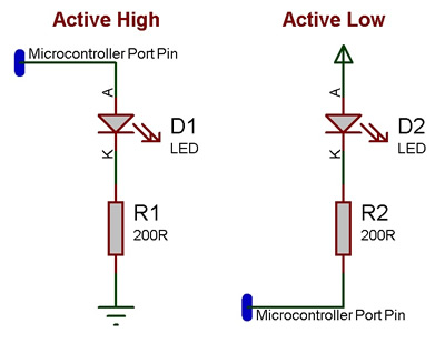
An active high LED will light when the microcontroller pin is outputting a logic 1 and be off when the microcontroller pin is outputting a logic 0 or in input mode.
An active low LED will light when the microcontroller pin is outputting a logic 0 and be off when the microcontroller pin is outputting a logic 1 or in input mode.
The series resistor can be on either side of the LED and acts to protect the LED from damage due to excess current. The value of resistor used can be changed based on the brightness of the LED and power consumption.
This LED Calculator tool is a good resource for calculating the correct LED series protection resistor.
LED Resistor Calculator Tool
Macro reference
AllOff

|
AllOff
|
| Turns off all elements
|
 - VOID - VOID
|
Return
|
AllOn
|
|
AllOn
|
| Turns on all elements
|
| - VOID
|
Return
|
BarGraph
|
|
BarGraph
|
| Turns on the first N elements of the array - for generating bar graph metes etc.
|
 - BYTE - BYTE
|
Length
|
| How many items to light up.
|
| - VOID
|
Return
|
LEDOff
|
|
LEDOff
|
| Turn off the selected led.
|
| - BYTE
|
Index
|
| Index of the LED to turn on.
|
| - VOID
|
Return
|
LEDOn
|
|
LEDOn
|
| Turn on the selected LED.
|
| - BYTE
|
Index
|
| Index of the LED to turn on.
|
| - VOID
|
Return
|
PointGraph
|
|
PointGraph
|
| Turns on the Indexed LED and turns all others off. Does nothing if the index is out of range.
|
| - BYTE
|
Index
|
| The LED to show.
|
| - VOID
|
Return
|
WriteValue
|
|
WriteValue
|
| Write a number which is presented on the LEDs in binary.
|
| - BYTE
|
Value
|
| Provide a value to be written to the LEDs in binary
|
| - VOID
|
Return
|
Property reference

|
Properties
|

|
Count
|
| The number of LEDs in the array from 1 to 8.
|

|
Connections
|
|
|
Output Mode
|
|
|

|
Port
|
|
|
|
|
Polarity
|
|
|
|
|
Simulation
|
|
|
Switch layout
|
|
|

|
Distance between LEDs
|
|
|

|
Label colour
|
|
|
|
|
Component Label
|
|
|

|
Show Connection Label
|
| If enabled, the pin designation will be shown, e.g. B0.
|
|
|
Show Pin Value
|
| Pin status of VCC or GND will be shown when enabled and simualtion is running.
|
|
|
Appearance
|
|
|
Shape
|
|
|
|
|
Colour
|
|
|
|
|
Style
|
|
|


 - VOID
 - BYTE


