|
|
| (14 intermediate revisions by 2 users not shown) |
| Line 2: |
Line 2: |
| |- | | |- |
| | width="20%" style="color:gray;" | Author | | | width="20%" style="color:gray;" | Author |
| | Matrix Ltd. | | | MatrixTSL |
| |- | | |- |
| | width="20%" style="color:gray;" | Version | | | width="20%" style="color:gray;" | Version |
| | 2.0 | | | 14.0 |
| |- | | |- |
| | width="20%" style="color:gray;" | Category | | | width="20%" style="color:gray;" | Category |
| Line 13: |
Line 13: |
|
| |
|
| ==Switch Array (Push) component== | | ==Switch Array (Push) component== |
| An array of up to eight momentary push switches, each connected to a single pin of the specified port. | | An array of up to eight push switches. In embedded mode each switch is connected to a single pin of the specified port. |
|
| |
|
| ==Component Source Code== | | ==Version information== |
|
| |
|
| Please click here to download the component source project: [https://www.flowcode.co.uk/wiki/componentsource/FC_Comp_Source_switch_array_push.fcfx FC_Comp_Source_switch_array_push.fcfx]
| | Library Version, Component Version, Date, Author, Info |
| | 12, 11.0, 26-06-24, MW, Removed [2D] from the component name |
| | 13, 13.0, 16-04-25, MW, Corrected bug when sim stopped Switch changed from on to off, but pin remained at VCC |
| | 13, 13.0, 16-04-25, MW, Fixed bug so individual customisation now works |
| | 13, 13.0, 16-04-25, MW, Created a new component icon |
| | 14, 14.0, 10-03-26, ST, Type, Label On/Off and Colour now transferred correctly |
| | |
|
| |
|
| Please click here to view the component source code (Beta): [https://www.flowcode.co.uk/FlowchartView/?wfile=componentsource/FC_Comp_Source_switch_array_push.fcfx FC_Comp_Source_switch_array_push.fcfx]
| |
|
| |
|
| ==Detailed description== | | ==Detailed description== |
| | |
| | |
|
| |
|
|
| |
|
| Line 44: |
Line 51: |
|
| |
|
| ==Examples== | | ==Examples== |
| | |
| | |
|
| |
|
|
| |
|
| Line 87: |
Line 96: |
| (5V / 11K) * 10K = 4.54545V | | (5V / 11K) * 10K = 4.54545V |
|
| |
|
| ==Macro reference==
| |
|
| |
| {| class="wikitable" style="width:60%; background-color:#FFFFFF;"
| |
| |-
| |
| | width="10%" align="center" style="background-color:#D8C9D8;" align="center" | [[File:Fc9-comp-macro.png]]
| |
| | width="90%" style="background-color:#D8C9D8; color:#4B008D;" | '''ReadState'''
| |
| |-
| |
| | colspan="2" | Read the state of the switch at the given index.
| |
| |-
| |
| |-
| |
| | width="10%" align="center" | [[File:Fc9-u8-icon.png]] - BYTE
| |
| | width="90%" | Index
| |
| |-
| |
| | colspan="2" | The switch to read the status of.
| |
| |-
| |
| | width="10%" align="center" style="border-top: 2px solid #000;" | [[File:Fc9-bool-icon.png]] - BOOL
| |
| | width="90%" style="border-top: 2px solid #000;" | ''Return''
| |
| |}
| |
|
| |
|
|
| |
|
| {| class="wikitable" style="width:60%; background-color:#FFFFFF;"
| |
| |-
| |
| | width="10%" align="center" style="background-color:#D8C9D8;" align="center" | [[File:Fc9-comp-macro.png]]
| |
| | width="90%" style="background-color:#D8C9D8; color:#4B008D;" | '''WaitUntilHigh'''
| |
| |-
| |
| | colspan="2" | Pause the program until the switch at the given index is turned on.
| |
| |-
| |
| |-
| |
| | width="10%" align="center" | [[File:Fc9-u8-icon.png]] - BYTE
| |
| | width="90%" | Index
| |
| |-
| |
| | colspan="2" | Index of the switch to wait for.
| |
| |-
| |
| | width="10%" align="center" style="border-top: 2px solid #000;" | [[File:Fc9-void-icon.png]] - VOID
| |
| | width="90%" style="border-top: 2px solid #000;" | ''Return''
| |
| |}
| |
|
| |
|
|
| |
|
| {| class="wikitable" style="width:60%; background-color:#FFFFFF;"
| |
| |-
| |
| | width="10%" align="center" style="background-color:#D8C9D8;" align="center" | [[File:Fc9-comp-macro.png]]
| |
| | width="90%" style="background-color:#D8C9D8; color:#4B008D;" | '''ReadAll'''
| |
| |-
| |
| | colspan="2" | Reads all of the switches at once, returning a byte containing one bit per switch.
| |
| |-
| |
| |-
| |
| | width="10%" align="center" style="border-top: 2px solid #000;" | [[File:Fc9-u8-icon.png]] - BYTE
| |
| | width="90%" style="border-top: 2px solid #000;" | ''Return''
| |
| |}
| |
|
| |
|
|
| |
|
| {| class="wikitable" style="width:60%; background-color:#FFFFFF;"
| |
| |-
| |
| | width="10%" align="center" style="background-color:#D8C9D8;" align="center" | [[File:Fc9-comp-macro.png]]
| |
| | width="90%" style="background-color:#D8C9D8; color:#4B008D;" | '''GetHandle'''
| |
| |-
| |
| | colspan="2" | Retrieves the object handle of the switch component at the given index.
| |
| |-
| |
| |-
| |
| | width="10%" align="center" | [[File:Fc9-u8-icon.png]] - BYTE
| |
| | width="90%" | Index
| |
| |-
| |
| | colspan="2" |
| |
| |-
| |
| | width="10%" align="center" style="border-top: 2px solid #000;" | [[File:Fc9-h32-icon.png]] - HANDLE
| |
| | width="90%" style="border-top: 2px solid #000;" | ''Return''
| |
| |}
| |
|
| |
|
|
| |
|
| {| class="wikitable" style="width:60%; background-color:#FFFFFF;"
| |
| |-
| |
| | width="10%" align="center" style="background-color:#D8C9D8;" align="center" | [[File:Fc9-comp-macro.png]]
| |
| | width="90%" style="background-color:#D8C9D8; color:#4B008D;" | '''WaitUntilLow'''
| |
| |-
| |
| | colspan="2" | Pause the program until the switch at the given index is turned on.
| |
| |-
| |
| |-
| |
| | width="10%" align="center" | [[File:Fc9-u8-icon.png]] - BYTE
| |
| | width="90%" | Index
| |
| |-
| |
| | colspan="2" | Index of the switch to wait for.
| |
| |-
| |
| | width="10%" align="center" style="border-top: 2px solid #000;" | [[File:Fc9-void-icon.png]] - VOID
| |
| | width="90%" style="border-top: 2px solid #000;" | ''Return''
| |
| |}
| |
|
| |
|
|
| |
|
|
| |
|
|
| |
|
| ==Property reference== | | ==Macro reference== |
|
| |
|
| {| class="wikitable" style="width:60%; background-color:#FFFFFF;" | | ===ReadAll=== |
| | {| class="mtx-class-macrotable wikitable" |
| |- | | |- |
| | width="10%" align="center" style="background-color:#D8C9D8;" | [[File:Fc9-prop-icon.png]] | | | width="10%" align="center" class="mtx-class-macrohead" | [[File:Fc9-comp-macro.png]] |
| | width="90%" style="background-color:#D8C9D8; color:#4B008D;" | '''Properties''' | | | width="90%" class="mtx-class-macrohead" | '''ReadAll''' |
| |- | | |- |
| | | colspan="2" | Reads all of the switches at once, returning a byte containing one bit per switch. |
| |- | | |- |
| | width="10%" align="center" | [[File:Fc9-type-16-icon.png]]
| |
| | width="90%" | Count
| |
| |- | | |- |
| | colspan="2" | The number of LEDs in the array from 1 to 8.
| | | width="10%" align="center" style="border-top: 2px solid #000;" | [[File:Fc9-u8-icon.png]] - BYTE |
| |-
| | | width="90%" style="border-top: 2px solid #000;" | ''Return'' |
| | width="10%" align="center" style="background-color:#EAE1EA;" | [[File:Fc9-conn-icon.png]] | | |} |
| | width="90%" style="background-color:#EAE1EA; color:#4B008D;" | Connections | | |
| |-
| |
| |-
| |
| | width="10%" align="center" | [[File:Fc9-type-16-icon.png]]
| |
| | width="90%" | Input Mode
| |
| |-
| |
| | colspan="2" | Choose a single port for all LEDs - pins are allocated in sequence from pin 0 - 7 ...or choose 'Custom pins' to assign each switch individually.
| |
| |-
| |
| | width="10%" align="center" | [[File:Fc9-type-19-icon.png]]
| |
| | width="90%" | Port
| |
| |-
| |
| | colspan="2" |
| |
| |-
| |
| | width="10%" align="center" | [[File:Fc9-type-16-icon.png]]
| |
| | width="90%" | Polarity
| |
| |-
| |
| | colspan="2" | Active High = LEDs light when the chosen chip pin is ON Active Low = LEDs light when the chosen chip pin is OFF
| |
| |-
| |
| | width="10%" align="center" | [[File:Fc9-type-14-icon.png]]
| |
| | width="90%" | Debounce
| |
| |-
| |
| | colspan="2" | Time in milliseconds allowed for the pin to settle following a change of state.
| |
| |-
| |
| | width="10%" align="center" | [[File:Fc9-type-16-icon.png]]
| |
| | width="90%" | Operation
| |
| |-
| |
| | colspan="2" | Sets whether switches toggle or are press/release. NB) This option can only be set when the original target includes this option.
| |
| |-
| |
| | width="10%" align="center" style="background-color:#EAE1EA;" | [[File:Fc9-conn-icon.png]]
| |
| | width="90%" style="background-color:#EAE1EA; color:#4B008D;" | Simulation
| |
| |-
| |
| |-
| |
| | width="10%" align="center" | [[File:Fc9-type-16-icon.png]]
| |
| | width="90%" | Alignment
| |
| |-
| |
| | colspan="2" | Which 3D axis to align the copies along.
| |
| |-
| |
| | width="10%" align="center" | [[File:Fc9-type-15-icon.png]]
| |
| | width="90%" | Spacing
| |
| |-
| |
| | colspan="2" | The distance between LEDs in the array. LEDs will be spaced symmetrically around the component centre. Use a negative value to reverse the order of the LEDs.
| |
| |-
| |
| | width="10%" align="center" | [[File:Fc9-type-7-icon.png]]
| |
| | width="90%" | Reverse
| |
| |-
| |
| | colspan="2" | Whether to reverse the order of the switches.
| |
| |-
| |
| | width="10%" align="center" | [[File:Fc9-type-16-icon.png]]
| |
| | width="90%" | Show Labels
| |
| |-
| |
| | colspan="2" | Whether to show labels giving each switch's pin connection.
| |
| |- | |
| | width="10%" align="center" | [[File:Fc9-type-1-icon.png]]
| |
| | width="90%" | Label color
| |
| |-
| |
| | colspan="2" | Color of the port and pin labels
| |
| |}==Macro reference==
| |
|
| |
|
| {| class="wikitable" style="width:60%; background-color:#FFFFFF;" | | ===ReadState=== |
| | {| class="mtx-class-macrotable wikitable" |
| |- | | |- |
| | width="10%" align="center" style="background-color:#D8C9D8;" align="center" | [[File:Fc9-comp-macro.png]] | | | width="10%" align="center" class="mtx-class-macrohead" | [[File:Fc9-comp-macro.png]] |
| | width="90%" style="background-color:#D8C9D8; color:#4B008D;" | '''ReadState''' | | | width="90%" class="mtx-class-macrohead" | '''ReadState''' |
| |- | | |- |
| | colspan="2" | Read the state of the switch at the given index. | | | colspan="2" | Read the state of the switch at the given index. |
| Line 266: |
Line 143: |
|
| |
|
|
| |
|
| {| class="wikitable" style="width:60%; background-color:#FFFFFF;" | | ===WaitUntilHigh=== |
| | {| class="mtx-class-macrotable wikitable" |
| |- | | |- |
| | width="10%" align="center" style="background-color:#D8C9D8;" align="center" | [[File:Fc9-comp-macro.png]] | | | width="10%" align="center" class="mtx-class-macrohead" | [[File:Fc9-comp-macro.png]] |
| | width="90%" style="background-color:#D8C9D8; color:#4B008D;" | '''WaitUntilHigh''' | | | width="90%" class="mtx-class-macrohead" | '''WaitUntilHigh''' |
| |- | | |- |
| | colspan="2" | Pause the program until the switch at the given index is turned on. | | | colspan="2" | Pause the program until the switch at the given index is turned on. |
| Line 284: |
Line 162: |
|
| |
|
|
| |
|
| {| class="wikitable" style="width:60%; background-color:#FFFFFF;"
| | ===WaitUntilLow=== |
| |-
| | {| class="mtx-class-macrotable wikitable" |
| | width="10%" align="center" style="background-color:#D8C9D8;" align="center" | [[File:Fc9-comp-macro.png]]
| |
| | width="90%" style="background-color:#D8C9D8; color:#4B008D;" | '''ReadAll'''
| |
| |-
| |
| | colspan="2" | Reads all of the switches at once, returning a byte containing one bit per switch.
| |
| |-
| |
| |-
| |
| | width="10%" align="center" style="border-top: 2px solid #000;" | [[File:Fc9-u8-icon.png]] - BYTE
| |
| | width="90%" style="border-top: 2px solid #000;" | ''Return''
| |
| |}
| |
| | |
| | |
| {| class="wikitable" style="width:60%; background-color:#FFFFFF;" | |
| |-
| |
| | width="10%" align="center" style="background-color:#D8C9D8;" align="center" | [[File:Fc9-comp-macro.png]]
| |
| | width="90%" style="background-color:#D8C9D8; color:#4B008D;" | '''GetHandle'''
| |
| |-
| |
| | colspan="2" | Retrieves the object handle of the switch component at the given index.
| |
| |-
| |
| |-
| |
| | width="10%" align="center" | [[File:Fc9-u8-icon.png]] - BYTE
| |
| | width="90%" | Index
| |
| |-
| |
| | colspan="2" |
| |
| |-
| |
| | width="10%" align="center" style="border-top: 2px solid #000;" | [[File:Fc9-h32-icon.png]] - HANDLE
| |
| | width="90%" style="border-top: 2px solid #000;" | ''Return''
| |
| |}
| |
| | |
| | |
| {| class="wikitable" style="width:60%; background-color:#FFFFFF;"
| |
| |- | | |- |
| | width="10%" align="center" style="background-color:#D8C9D8;" align="center" | [[File:Fc9-comp-macro.png]] | | | width="10%" align="center" class="mtx-class-macrohead" | [[File:Fc9-comp-macro.png]] |
| | width="90%" style="background-color:#D8C9D8; color:#4B008D;" | '''WaitUntilLow''' | | | width="90%" class="mtx-class-macrohead" | '''WaitUntilLow''' |
| |- | | |- |
| | colspan="2" | Pause the program until the switch at the given index is turned on. | | | colspan="2" | Pause the program until the switch at the given index is turned on. |
| Line 331: |
Line 179: |
| | width="90%" style="border-top: 2px solid #000;" | ''Return'' | | | width="90%" style="border-top: 2px solid #000;" | ''Return'' |
| |} | | |} |
|
| |
|
| |
|
| |
|
|
| |
|
| ==Property reference== | | ==Property reference== |
|
| |
|
| {| class="wikitable" style="width:60%; background-color:#FFFFFF;" | | {| class="mtx-class-macrotable wikitable" |
| |- | | |- |
| | width="10%" align="center" style="background-color:#D8C9D8;" | [[File:Fc9-prop-icon.png]] | | | width="10%" align="center" class="mtx-class-macrohead" | [[File:Fc9-prop-icon.png]] |
| | width="90%" style="background-color:#D8C9D8; color:#4B008D;" | '''Properties''' | | | width="90%" class="mtx-class-macrohead" | '''Properties''' |
| |- | | |- |
| |- | | |- |
| Line 348: |
Line 194: |
| | colspan="2" | The number of LEDs in the array from 1 to 8. | | | colspan="2" | The number of LEDs in the array from 1 to 8. |
| |- | | |- |
| | width="10%" align="center" style="background-color:#EAE1EA;" | [[File:Fc9-conn-icon.png]] | | | width="10%" align="center" class="mtx-class-propfolder" | [[File:Fc9-conn-icon.png]] |
| | width="90%" style="background-color:#EAE1EA; color:#4B008D;" | Connections | | | width="90%" class="mtx-class-propfolder" | Function |
| |- | | |- |
| |-
| |
| | width="10%" align="center" | [[File:Fc9-type-16-icon.png]]
| |
| | width="90%" | Input Mode
| |
| |-
| |
| | colspan="2" | Choose a single port for all LEDs - pins are allocated in sequence from pin 0 - 7 ...or choose 'Custom pins' to assign each switch individually.
| |
| |-
| |
| | width="10%" align="center" | [[File:Fc9-type-19-icon.png]]
| |
| | width="90%" | Port
| |
| |-
| |
| | colspan="2" |
| |
| |-
| |
| | width="10%" align="center" | [[File:Fc9-type-16-icon.png]]
| |
| | width="90%" | Polarity
| |
| |-
| |
| | colspan="2" | Active High = LEDs light when the chosen chip pin is ON Active Low = LEDs light when the chosen chip pin is OFF
| |
| |-
| |
| | width="10%" align="center" | [[File:Fc9-type-14-icon.png]]
| |
| | width="90%" | Debounce
| |
| |-
| |
| | colspan="2" | Time in milliseconds allowed for the pin to settle following a change of state.
| |
| |-
| |
| | width="10%" align="center" | [[File:Fc9-type-16-icon.png]]
| |
| | width="90%" | Operation
| |
| |-
| |
| | colspan="2" | Sets whether switches toggle or are press/release. NB) This option can only be set when the original target includes this option.
| |
| |-
| |
| | width="10%" align="center" style="background-color:#EAE1EA;" | [[File:Fc9-conn-icon.png]]
| |
| | width="90%" style="background-color:#EAE1EA; color:#4B008D;" | Simulation
| |
| |-
| |
| |-
| |
| | width="10%" align="center" | [[File:Fc9-type-16-icon.png]]
| |
| | width="90%" | Alignment
| |
| |-
| |
| | colspan="2" | Which 3D axis to align the copies along.
| |
| |-
| |
| | width="10%" align="center" | [[File:Fc9-type-15-icon.png]]
| |
| | width="90%" | Spacing
| |
| |-
| |
| | colspan="2" | The distance between LEDs in the array. LEDs will be spaced symmetrically around the component centre. Use a negative value to reverse the order of the LEDs.
| |
| |- | | |- |
| | width="10%" align="center" | [[File:Fc9-type-7-icon.png]] | | | width="10%" align="center" | [[File:Fc9-type-7-icon.png]] |
| | width="90%" | Reverse | | | width="90%" | Simulation Only |
| |-
| |
| | colspan="2" | Whether to reverse the order of the switches.
| |
| |-
| |
| | width="10%" align="center" | [[File:Fc9-type-16-icon.png]]
| |
| | width="90%" | Show Labels
| |
| |-
| |
| | colspan="2" | Whether to show labels giving each switch's pin connection.
| |
| |-
| |
| | width="10%" align="center" | [[File:Fc9-type-1-icon.png]]
| |
| | width="90%" | Label color
| |
| |-
| |
| | colspan="2" | Color of the port and pin labels
| |
| |}==Macro reference==
| |
| | |
| {| class="wikitable" style="width:60%; background-color:#FFFFFF;"
| |
| |-
| |
| | width="10%" align="center" style="background-color:#D8C9D8;" align="center" | [[File:Fc9-comp-macro.png]]
| |
| | width="90%" style="background-color:#D8C9D8; color:#4B008D;" | '''ReadState'''
| |
| |-
| |
| | colspan="2" | Read the state of the switch at the given index.
| |
| |-
| |
| |-
| |
| | width="10%" align="center" | [[File:Fc9-u8-icon.png]] - BYTE
| |
| | width="90%" | Index
| |
| |-
| |
| | colspan="2" | The switch to read the status of.
| |
| |-
| |
| | width="10%" align="center" style="border-top: 2px solid #000;" | [[File:Fc9-bool-icon.png]] - BOOL
| |
| | width="90%" style="border-top: 2px solid #000;" | ''Return''
| |
| |}
| |
| | |
| | |
| {| class="wikitable" style="width:60%; background-color:#FFFFFF;"
| |
| |-
| |
| | width="10%" align="center" style="background-color:#D8C9D8;" align="center" | [[File:Fc9-comp-macro.png]]
| |
| | width="90%" style="background-color:#D8C9D8; color:#4B008D;" | '''WaitUntilHigh'''
| |
| |-
| |
| | colspan="2" | Pause the program until the switch at the given index is turned on.
| |
| |-
| |
| |-
| |
| | width="10%" align="center" | [[File:Fc9-u8-icon.png]] - BYTE
| |
| | width="90%" | Index
| |
| |-
| |
| | colspan="2" | Index of the switch to wait for.
| |
| |-
| |
| | width="10%" align="center" style="border-top: 2px solid #000;" | [[File:Fc9-void-icon.png]] - VOID
| |
| | width="90%" style="border-top: 2px solid #000;" | ''Return''
| |
| |}
| |
| | |
| | |
| {| class="wikitable" style="width:60%; background-color:#FFFFFF;"
| |
| |-
| |
| | width="10%" align="center" style="background-color:#D8C9D8;" align="center" | [[File:Fc9-comp-macro.png]]
| |
| | width="90%" style="background-color:#D8C9D8; color:#4B008D;" | '''ReadAll'''
| |
| |-
| |
| | colspan="2" | Reads all of the switches at once, returning a byte containing one bit per switch.
| |
| |-
| |
| |-
| |
| | width="10%" align="center" style="border-top: 2px solid #000;" | [[File:Fc9-u8-icon.png]] - BYTE
| |
| | width="90%" style="border-top: 2px solid #000;" | ''Return''
| |
| |}
| |
| | |
| | |
| {| class="wikitable" style="width:60%; background-color:#FFFFFF;"
| |
| |-
| |
| | width="10%" align="center" style="background-color:#D8C9D8;" align="center" | [[File:Fc9-comp-macro.png]]
| |
| | width="90%" style="background-color:#D8C9D8; color:#4B008D;" | '''GetHandle'''
| |
| |-
| |
| | colspan="2" | Retrieves the object handle of the switch component at the given index.
| |
| |-
| |
| |-
| |
| | width="10%" align="center" | [[File:Fc9-u8-icon.png]] - BYTE
| |
| | width="90%" | Index
| |
| |- | | |- |
| | colspan="2" | | | | colspan="2" | |
| |- | | |- |
| | width="10%" align="center" style="border-top: 2px solid #000;" | [[File:Fc9-h32-icon.png]] - HANDLE | | | width="10%" align="center" class="mtx-class-propfolder" | [[File:Fc9-conn-icon.png]] |
| | width="90%" style="border-top: 2px solid #000;" | ''Return''
| | | width="90%" class="mtx-class-propfolder" | Switch Settings |
| |}
| |
| | |
| | |
| {| class="wikitable" style="width:60%; background-color:#FFFFFF;"
| |
| |-
| |
| | width="10%" align="center" style="background-color:#D8C9D8;" align="center" | [[File:Fc9-comp-macro.png]]
| |
| | width="90%" style="background-color:#D8C9D8; color:#4B008D;" | '''WaitUntilLow'''
| |
| |-
| |
| | colspan="2" | Pause the program until the switch at the given index is turned on.
| |
| |-
| |
| |-
| |
| | width="10%" align="center" | [[File:Fc9-u8-icon.png]] - BYTE
| |
| | width="90%" | Index | |
| |-
| |
| | colspan="2" | Index of the switch to wait for.
| |
| |-
| |
| | width="10%" align="center" style="border-top: 2px solid #000;" | [[File:Fc9-void-icon.png]] - VOID
| |
| | width="90%" style="border-top: 2px solid #000;" | ''Return''
| |
| |}
| |
| | |
| | |
| | |
| | |
| ==Property reference==
| |
| | |
| {| class="wikitable" style="width:60%; background-color:#FFFFFF;"
| |
| |-
| |
| | width="10%" align="center" style="background-color:#D8C9D8;" | [[File:Fc9-prop-icon.png]]
| |
| | width="90%" style="background-color:#D8C9D8; color:#4B008D;" | '''Properties'''
| |
| |-
| |
| |-
| |
| | width="10%" align="center" | [[File:Fc9-type-16-icon.png]]
| |
| | width="90%" | Count
| |
| |-
| |
| | colspan="2" | The number of LEDs in the array from 1 to 8.
| |
| |-
| |
| | width="10%" align="center" style="background-color:#EAE1EA;" | [[File:Fc9-conn-icon.png]]
| |
| | width="90%" style="background-color:#EAE1EA; color:#4B008D;" | Connections
| |
| |- | | |- |
| |- | | |- |
| Line 536: |
Line 232: |
| | colspan="2" | Sets whether switches toggle or are press/release. NB) This option can only be set when the original target includes this option. | | | colspan="2" | Sets whether switches toggle or are press/release. NB) This option can only be set when the original target includes this option. |
| |- | | |- |
| | width="10%" align="center" style="background-color:#EAE1EA;" | [[File:Fc9-conn-icon.png]] | | | width="10%" align="center" class="mtx-class-propfolder" | [[File:Fc9-conn-icon.png]] |
| | width="90%" style="background-color:#EAE1EA; color:#4B008D;" | Simulation | | | width="90%" class="mtx-class-propfolder" | Appearance |
| |- | | |- |
| |- | | |- |
| | width="10%" align="center" | [[File:Fc9-type-16-icon.png]] | | | width="10%" align="center" | [[File:Fc9-type-16-icon.png]] |
| | width="90%" | Alignment | | | width="90%" | Component Label |
| |-
| |
| | colspan="2" | Which 3D axis to align the copies along.
| |
| |-
| |
| | width="10%" align="center" | [[File:Fc9-type-15-icon.png]]
| |
| | width="90%" | Spacing
| |
| |-
| |
| | colspan="2" | The distance between LEDs in the array. LEDs will be spaced symmetrically around the component centre. Use a negative value to reverse the order of the LEDs.
| |
| |-
| |
| | width="10%" align="center" | [[File:Fc9-type-7-icon.png]]
| |
| | width="90%" | Reverse
| |
| |- | | |- |
| | colspan="2" | Whether to reverse the order of the switches. | | | colspan="2" | Allows you to add your own label to each switch. If Same as Handle is selected then all custom text will be erased. |
| |- | | |- |
| | width="10%" align="center" | [[File:Fc9-type-16-icon.png]] | | | width="10%" align="center" | [[File:Fc9-type-16-icon.png]] |
| | width="90%" | Show Labels | | | width="90%" | Switch layout |
| |-
| |
| | colspan="2" | Whether to show labels giving each switch's pin connection.
| |
| |-
| |
| | width="10%" align="center" | [[File:Fc9-type-1-icon.png]]
| |
| | width="90%" | Label color
| |
| |-
| |
| | colspan="2" | Color of the port and pin labels
| |
| |}==Macro reference==
| |
| | |
| {| class="wikitable" style="width:60%; background-color:#FFFFFF;"
| |
| |-
| |
| | width="10%" align="center" style="background-color:#D8C9D8;" align="center" | [[File:Fc9-comp-macro.png]]
| |
| | width="90%" style="background-color:#D8C9D8; color:#4B008D;" | '''ReadState'''
| |
| |-
| |
| | colspan="2" | Read the state of the switch at the given index.
| |
| |-
| |
| |-
| |
| | width="10%" align="center" | [[File:Fc9-u8-icon.png]] - BYTE
| |
| | width="90%" | Index
| |
| |-
| |
| | colspan="2" | The switch to read the status of.
| |
| |-
| |
| | width="10%" align="center" style="border-top: 2px solid #000;" | [[File:Fc9-bool-icon.png]] - BOOL
| |
| | width="90%" style="border-top: 2px solid #000;" | ''Return''
| |
| |}
| |
| | |
| | |
| {| class="wikitable" style="width:60%; background-color:#FFFFFF;"
| |
| |-
| |
| | width="10%" align="center" style="background-color:#D8C9D8;" align="center" | [[File:Fc9-comp-macro.png]]
| |
| | width="90%" style="background-color:#D8C9D8; color:#4B008D;" | '''WaitUntilHigh'''
| |
| |-
| |
| | colspan="2" | Pause the program until the switch at the given index is turned on.
| |
| |-
| |
| |-
| |
| | width="10%" align="center" | [[File:Fc9-u8-icon.png]] - BYTE
| |
| | width="90%" | Index
| |
| |-
| |
| | colspan="2" | Index of the switch to wait for.
| |
| |-
| |
| | width="10%" align="center" style="border-top: 2px solid #000;" | [[File:Fc9-void-icon.png]] - VOID
| |
| | width="90%" style="border-top: 2px solid #000;" | ''Return''
| |
| |}
| |
| | |
| | |
| {| class="wikitable" style="width:60%; background-color:#FFFFFF;"
| |
| |-
| |
| | width="10%" align="center" style="background-color:#D8C9D8;" align="center" | [[File:Fc9-comp-macro.png]]
| |
| | width="90%" style="background-color:#D8C9D8; color:#4B008D;" | '''ReadAll'''
| |
| |-
| |
| | colspan="2" | Reads all of the switches at once, returning a byte containing one bit per switch.
| |
| |-
| |
| |-
| |
| | width="10%" align="center" style="border-top: 2px solid #000;" | [[File:Fc9-u8-icon.png]] - BYTE
| |
| | width="90%" style="border-top: 2px solid #000;" | ''Return''
| |
| |}
| |
| | |
| | |
| {| class="wikitable" style="width:60%; background-color:#FFFFFF;"
| |
| |-
| |
| | width="10%" align="center" style="background-color:#D8C9D8;" align="center" | [[File:Fc9-comp-macro.png]]
| |
| | width="90%" style="background-color:#D8C9D8; color:#4B008D;" | '''GetHandle'''
| |
| |-
| |
| | colspan="2" | Retrieves the object handle of the switch component at the given index.
| |
| |-
| |
| |-
| |
| | width="10%" align="center" | [[File:Fc9-u8-icon.png]] - BYTE
| |
| | width="90%" | Index
| |
| |- | | |- |
| | colspan="2" | | | | colspan="2" | |
| |- | | |- |
| | width="10%" align="center" style="border-top: 2px solid #000;" | [[File:Fc9-h32-icon.png]] - HANDLE | | | width="10%" align="center" | [[File:Fc9-type-21-icon.png]] |
| | width="90%" style="border-top: 2px solid #000;" | ''Return''
| | | width="90%" | Distance between switches |
| |}
| |
| | |
| | |
| {| class="wikitable" style="width:60%; background-color:#FFFFFF;"
| |
| |-
| |
| | width="10%" align="center" style="background-color:#D8C9D8;" align="center" | [[File:Fc9-comp-macro.png]]
| |
| | width="90%" style="background-color:#D8C9D8; color:#4B008D;" | '''WaitUntilLow'''
| |
| |-
| |
| | colspan="2" | Pause the program until the switch at the given index is turned on.
| |
| |-
| |
| |-
| |
| | width="10%" align="center" | [[File:Fc9-u8-icon.png]] - BYTE
| |
| | width="90%" | Index | |
| |-
| |
| | colspan="2" | Index of the switch to wait for.
| |
| |-
| |
| | width="10%" align="center" style="border-top: 2px solid #000;" | [[File:Fc9-void-icon.png]] - VOID
| |
| | width="90%" style="border-top: 2px solid #000;" | ''Return''
| |
| |}
| |
| | |
| | |
| | |
| | |
| ==Property reference==
| |
| | |
| {| class="wikitable" style="width:60%; background-color:#FFFFFF;"
| |
| |-
| |
| | width="10%" align="center" style="background-color:#D8C9D8;" | [[File:Fc9-prop-icon.png]]
| |
| | width="90%" style="background-color:#D8C9D8; color:#4B008D;" | '''Properties'''
| |
| |- | | |- |
| | | colspan="2" | Set distance betwwn each switch. Default = 55 |
| |- | | |- |
| | width="10%" align="center" | [[File:Fc9-type-16-icon.png]] | | | width="10%" align="center" | [[File:Fc9-type-16-icon.png]] |
| | width="90%" | Count | | | width="90%" | Style |
| |-
| |
| | colspan="2" | The number of LEDs in the array from 1 to 8.
| |
| |-
| |
| | width="10%" align="center" style="background-color:#EAE1EA;" | [[File:Fc9-conn-icon.png]]
| |
| | width="90%" style="background-color:#EAE1EA; color:#4B008D;" | Connections
| |
| |- | | |- |
| | | colspan="2" | |
| |- | | |- |
| | width="10%" align="center" | [[File:Fc9-type-16-icon.png]] | | | width="10%" align="center" | [[File:Fc9-type-16-icon.png]] |
| | width="90%" | Input Mode | | | width="90%" | Type |
| |- | | |- |
| | colspan="2" | Choose a single port for all LEDs - pins are allocated in sequence from pin 0 - 7 ...or choose 'Custom pins' to assign each switch individually. | | | colspan="2" | |
| |- | | |- |
| | width="10%" align="center" | [[File:Fc9-type-19-icon.png]] | | | width="10%" align="center" | [[File:Fc9-type-10-icon.png]] |
| | width="90%" | Port | | | width="90%" | On Label |
| |- | | |- |
| | colspan="2" | | | | colspan="2" | |
| |- | | |- |
| | width="10%" align="center" | [[File:Fc9-type-16-icon.png]] | | | width="10%" align="center" | [[File:Fc9-type-10-icon.png]] |
| | width="90%" | Polarity | | | width="90%" | Off Label |
| |- | | |- |
| | colspan="2" | Active High = LEDs light when the chosen chip pin is ON Active Low = LEDs light when the chosen chip pin is OFF | | | colspan="2" | |
| |- | | |- |
| | width="10%" align="center" | [[File:Fc9-type-14-icon.png]] | | | width="10%" align="center" | [[File:Fc9-type-1-icon.png]] |
| | width="90%" | Debounce | | | width="90%" | Label Colour |
| |- | | |- |
| | colspan="2" | Time in milliseconds allowed for the pin to settle following a change of state. | | | colspan="2" | |
| |- | | |- |
| | width="10%" align="center" | [[File:Fc9-type-16-icon.png]] | | | width="10%" align="center" | [[File:Fc9-type-7-icon.png]] |
| | width="90%" | Operation | | | width="90%" | Show Connection Label |
| |- | | |- |
| | colspan="2" | Sets whether switches toggle or are press/release. NB) This option can only be set when the original target includes this option. | | | colspan="2" | |
| |-
| |
| | width="10%" align="center" style="background-color:#EAE1EA;" | [[File:Fc9-conn-icon.png]]
| |
| | width="90%" style="background-color:#EAE1EA; color:#4B008D;" | Simulation
| |
| |-
| |
| |-
| |
| | width="10%" align="center" | [[File:Fc9-type-16-icon.png]]
| |
| | width="90%" | Alignment
| |
| |-
| |
| | colspan="2" | Which 3D axis to align the copies along.
| |
| |-
| |
| | width="10%" align="center" | [[File:Fc9-type-15-icon.png]]
| |
| | width="90%" | Spacing
| |
| |-
| |
| | colspan="2" | The distance between LEDs in the array. LEDs will be spaced symmetrically around the component centre. Use a negative value to reverse the order of the LEDs.
| |
| |- | | |- |
| | width="10%" align="center" | [[File:Fc9-type-7-icon.png]] | | | width="10%" align="center" | [[File:Fc9-type-7-icon.png]] |
| | width="90%" | Reverse | | | width="90%" | Show Pin Value |
| |- | | |- |
| | colspan="2" | Whether to reverse the order of the switches. | | | colspan="2" | |
| |-
| |
| | width="10%" align="center" | [[File:Fc9-type-16-icon.png]]
| |
| | width="90%" | Show Labels
| |
| |-
| |
| | colspan="2" | Whether to show labels giving each switch's pin connection.
| |
| |-
| |
| | width="10%" align="center" | [[File:Fc9-type-1-icon.png]]
| |
| | width="90%" | Label color
| |
| |-
| |
| | colspan="2" | Color of the port and pin labels
| |
| |} | | |} |
| | |
| | ==Component Source Code== |
| | |
| | Please click here to download the component source project: [https://www.flowcode.co.uk/wiki/componentsource/FC_Comp_Source_Switch_Array_Push_2dgi.fcfx FC_Comp_Source_Switch_Array_Push_2dgi.fcfx] |
| | |
| | Please click here to view the component source code (Beta): [https://www.flowcode.co.uk/FlowchartView/?wfile=componentsource/FC_Comp_Source_Switch_Array_Push_2dgi.fcfx FC_Comp_Source_Switch_Array_Push_2dgi.fcfx] |
| Author
|
MatrixTSL
|
| Version
|
14.0
|
| Category
|
Switches
|
Switch Array (Push) component
An array of up to eight push switches. In embedded mode each switch is connected to a single pin of the specified port.
Library Version, Component Version, Date, Author, Info
12, 11.0, 26-06-24, MW, Removed [2D] from the component name
13, 13.0, 16-04-25, MW, Corrected bug when sim stopped Switch changed from on to off, but pin remained at VCC
13, 13.0, 16-04-25, MW, Fixed bug so individual customisation now works
 13, 13.0, 16-04-25, MW, Created a new component icon
14, 14.0, 10-03-26, ST, Type, Label On/Off and Colour now transferred correctly
Detailed description
No detailed description exists yet for this component
Examples
Here is an example Flowcode program to read the values of a switch array.
 Switch Array
Here is a schematic of how to connect a basic switch to a microcontroller pin.
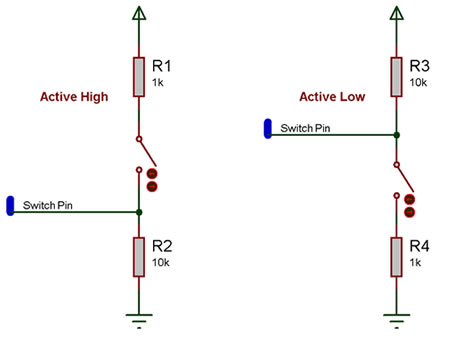
The active high circuit will pass a logical 0 to the input pin when the switch is not pressed and a logical 1 when the switch is pressed.
The active low circuit will pass a logical 1 to the input pin when the switch is not pressed and a logical 0 when the switch is pressed.
There are some differences depending on the type of switch you have, the above states assume a generic push to make type switch, however a push to break type switch would have reversed logic and a toggle switch can work well with either setup.
The resistors are required for correct operation because when a microcontroller's input pin is essentially connected to nothing it will pick up noise in the environment and provide inconsistent readings. This state is referred to as floating i.e. the pin is floating. To test this remove the resistors (if possible) and touch the unconnected pin with your finger the output LED from the example file above will toggle on and off at high speed.
Any values of resistor can be used but it is important to keep the smaller resistor at least 10X smaller then the larger resistor to ensure that the pressed state provides at least 0.91% of the required pressed state voltage. For example a active high switch circuit using 1K and 10K resistors should pull up to about 4.54V when the switch is pressed.
(5V / 11K) * 10K = 4.54545V
Macro reference
ReadAll

|
ReadAll
|
| Reads all of the switches at once, returning a byte containing one bit per switch.
|
 - BYTE - BYTE
|
Return
|
ReadState
|
|
ReadState
|
| Read the state of the switch at the given index.
|
| - BYTE
|
Index
|
| The switch to read the status of.
|
 - BOOL - BOOL
|
Return
|
WaitUntilHigh
|
|
WaitUntilHigh
|
| Pause the program until the switch at the given index is turned on.
|
| - BYTE
|
Index
|
| Index of the switch to wait for.
|
 - VOID - VOID
|
Return
|
WaitUntilLow
|
|
WaitUntilLow
|
| Pause the program until the switch at the given index is turned on.
|
| - BYTE
|
Index
|
| Index of the switch to wait for.
|
| - VOID
|
Return
|
Property reference

|
Properties
|

|
Count
|
| The number of LEDs in the array from 1 to 8.
|

|
Function
|

|
Simulation Only
|
|
|
|
|
Switch Settings
|
|
|
Input Mode
|
| Choose a single port for all LEDs - pins are allocated in sequence from pin 0 - 7 ...or choose 'Custom pins' to assign each switch individually.
|

|
Port
|
|
|
|
|
Polarity
|
| Active High = LEDs light when the chosen chip pin is ON Active Low = LEDs light when the chosen chip pin is OFF
|

|
Debounce
|
| Time in milliseconds allowed for the pin to settle following a change of state.
|
|
|
Operation
|
| Sets whether switches toggle or are press/release. NB) This option can only be set when the original target includes this option.
|
|
|
Appearance
|
|
|
Component Label
|
| Allows you to add your own label to each switch. If Same as Handle is selected then all custom text will be erased.
|
|
|
Switch layout
|
|
|

|
Distance between switches
|
| Set distance betwwn each switch. Default = 55
|
|
|
Style
|
|
|
|
|
Type
|
|
|

|
On Label
|
|
|
|
|
Off Label
|
|
|

|
Label Colour
|
|
|
|
|
Show Connection Label
|
|
|
|
|
Show Pin Value
|
|
|
Component Source Code
Please click here to download the component source project: FC_Comp_Source_Switch_Array_Push_2dgi.fcfx
Please click here to view the component source code (Beta): FC_Comp_Source_Switch_Array_Push_2dgi.fcfx


 - BYTE
 - BOOL
 - VOID


