Difference between revisions of "Component: ADC dial ()"
| (7 intermediate revisions by the same user not shown) | |||
| Line 17: | Line 17: | ||
==Component Source Code== | ==Component Source Code== | ||
| − | Please click here | + | Please click here to download the component source project: [https://www.flowcode.co.uk/wiki/componentsource/FC_Comp_Source_adc_dial.fcfx FC_Comp_Source_adc_dial.fcfx] |
| + | |||
| + | Please click here to view the component source code (Beta): [https://www.flowcode.co.uk/FlowchartView/?wfile=componentsource/FC_Comp_Source_adc_dial.fcfx FC_Comp_Source_adc_dial.fcfx] | ||
==Detailed description== | ==Detailed description== | ||
| + | |||
| + | |||
| + | |||
| + | |||
| + | |||
| + | |||
| + | |||
| + | |||
| Line 34: | Line 44: | ||
==Examples== | ==Examples== | ||
| + | |||
| + | |||
| + | |||
| + | |||
| + | |||
| + | |||
| + | |||
| + | |||
| Line 102: | Line 120: | ||
Based on the Scope Traces component property. | Based on the Scope Traces component property. | ||
| − | |||
| + | |||
| + | |||
| + | |||
| + | |||
| + | |||
| + | |||
| + | |||
| + | |||
| + | ==Macro reference== | ||
==Property reference== | ==Property reference== | ||
Latest revision as of 13:13, 7 February 2023
| Author | MatrixTSL |
| Version | 1.3 |
| Category |
Contents
ADC dial component
An ADC component represented by a dial
Component Source Code
Please click here to download the component source project: FC_Comp_Source_adc_dial.fcfx
Please click here to view the component source code (Beta): FC_Comp_Source_adc_dial.fcfx
Detailed description
No detailed description exists yet for this component
Examples
Read a 8-bit Byte
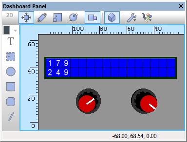
Simple ADC example allowing analogue values to be read on ADC inputs AN0 and AN1 as a byte, these are then displayed on the LCD connected to PortB as a number ranging from 0-255 representing 0V to VCC.
Read a 10-bit or 12-bit sample
Simple ADC example allowing analogue values to be read on ADC inputs AN0 and AN1 as a 10 or 12-bit value depending on the target microcontroller, these are then displayed on the LCD connected to PortB as a number ranging from 0-1023 or 0-4095 representing 0V to VCC.
Reading a sample as a Voltage
Simple ADC example allowing analogue Voltages to be read on ADC inputs AN0 and AN1, these are then displayed on the LCD connected to PortB in Volts from 0.0V-VCC. The VRef Voltage property needs to be correct for the Voltage to be calculated correctly.
Filtering ADC Inputs
Simple example which uses a filtering technique to provide a digital low pass filter on the ADC readings. The output of the filter is 50% the ADC reading and 50% the previous reading.
In this example the output of the filter is 25% the ADC reading and 75% the previous reading.
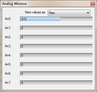
Analogue Inputs Window
The Analogue inputs window available from the View menu allows you to see the values for all of the analogue inputs which are active in your program. They can also be manually altered by dragging the mouse along one of the sliders.
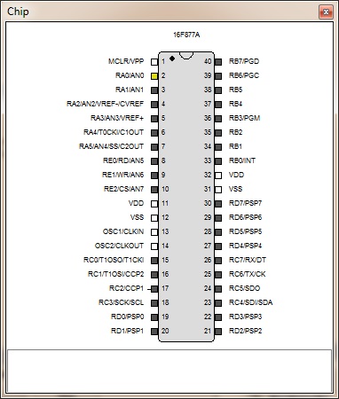
Chip Diagram
Active analogue inputs are highlighted in yellow on the chip diagram.
Scope Window
An ADC based component will automatically add a trace to the data recorder window allowing you to get a view of the analogue data over time during simulation.
Based on the Scope Traces component property.


