|
|
| (2 intermediate revisions by the same user not shown) |
| Line 14: |
Line 14: |
| | ==ADC Template component== | | ==ADC Template component== |
| | Base ADC component with no graphical interface. Contains all of the embedded side component calls to provide an ADC interface suitable for wrapping with a new ADC style component. | | Base ADC component with no graphical interface. Contains all of the embedded side component calls to provide an ADC interface suitable for wrapping with a new ADC style component. |
| − |
| |
| − | ==Component Source Code==
| |
| − |
| |
| − | Please click here to download the component source project: [https://www.flowcode.co.uk/wiki/componentsource/FC_Comp_Source_temp/adc_Base.fcfx FC_Comp_Source_temp/adc_Base.fcfx]
| |
| − |
| |
| − | Please click here to view the component source code (Beta): [https://www.flowcode.co.uk/FlowchartView/?wfile=componentsource/FC_Comp_Source_temp/adc_Base.fcfx FC_Comp_Source_temp/adc_Base.fcfx]
| |
| | | | |
| | ==Detailed description== | | ==Detailed description== |
| Line 103: |
Line 97: |
| | | | |
| | Based on the Scope Traces component property. | | Based on the Scope Traces component property. |
| | + | |
| | + | |
| | + | |
| | + | |
| | | | |
| | | | |
| Line 184: |
Line 182: |
| | |- | | |- |
| | | width="10%" align="center" style="border-top: 2px solid #000;" | [[File:Fc9-u16-icon.png]] - UINT | | | width="10%" align="center" style="border-top: 2px solid #000;" | [[File:Fc9-u16-icon.png]] - UINT |
| − | | width="90%" style="border-top: 2px solid #000;" | ''Return''
| |
| − | |}
| |
| − |
| |
| − |
| |
| − | ===GetSampleBits===
| |
| − | {| class="wikitable" style="width:60%; background-color:#FFFFFF;"
| |
| − | |-
| |
| − | | width="10%" align="center" style="background-color:#D8C9D8;" align="center" | [[File:Fc9-comp-macro.png]]
| |
| − | | width="90%" style="background-color:#D8C9D8; color:#4B008D;" | '''GetSampleBits'''
| |
| − | |-
| |
| − | | colspan="2" | Gets the number of bits per sample
| |
| − | |-
| |
| − | |-
| |
| − | | width="10%" align="center" style="border-top: 2px solid #000;" | [[File:Fc9-u8-icon.png]] - BYTE
| |
| − | | width="90%" style="border-top: 2px solid #000;" | ''Return''
| |
| − | |}
| |
| − |
| |
| − |
| |
| − | ===GetSpeedFilter===
| |
| − | {| class="wikitable" style="width:60%; background-color:#FFFFFF;"
| |
| − | |-
| |
| − | | width="10%" align="center" style="background-color:#D8C9D8;" align="center" | [[File:Fc9-comp-macro.png]]
| |
| − | | width="90%" style="background-color:#D8C9D8; color:#4B008D;" | '''GetSpeedFilter'''
| |
| − | |-
| |
| − | | colspan="2" | Gets the Conversion speed filter string Use in Component.Property.SetFilter()
| |
| − | |-
| |
| − | |-
| |
| − | | width="10%" align="center" style="border-top: 2px solid #000;" | [[File:Fc9-string-icon.png]] - STRING
| |
| | | width="90%" style="border-top: 2px solid #000;" | ''Return'' | | | width="90%" style="border-top: 2px solid #000;" | ''Return'' |
| | |} | | |} |
| Line 242: |
Line 212: |
| | | width="90%" style="border-top: 2px solid #000;" | ''Return'' | | | width="90%" style="border-top: 2px solid #000;" | ''Return'' |
| | |} | | |} |
| − |
| |
| − |
| |
| − | ===RawAverageByte===
| |
| − | {| class="wikitable" style="width:60%; background-color:#FFFFFF;"
| |
| − | |-
| |
| − | | width="10%" align="center" style="background-color:#D8C9D8;" align="center" | [[File:Fc9-comp-macro.png]]
| |
| − | | width="90%" style="background-color:#D8C9D8; color:#4B008D;" | '''RawAverageByte'''
| |
| − | |-
| |
| − | | colspan="2" | Background call to read the ADC as a byte average sample over time Call Enable() before this
| |
| − | |-
| |
| − | |-
| |
| − | | width="10%" align="center" | [[File:Fc9-u8-icon.png]] - BYTE
| |
| − | | width="90%" | NumSamples
| |
| − | |-
| |
| − | | colspan="2" |
| |
| − | |-
| |
| − | | width="10%" align="center" | [[File:Fc9-u8-icon.png]] - BYTE
| |
| − | | width="90%" | DelayUs
| |
| − | |-
| |
| − | | colspan="2" | Number of micro seconds in between taking each sample
| |
| − | |-
| |
| − | | width="10%" align="center" style="border-top: 2px solid #000;" | [[File:Fc9-u8-icon.png]] - BYTE
| |
| − | | width="90%" style="border-top: 2px solid #000;" | ''Return''
| |
| − | |}
| |
| − |
| |
| − |
| |
| − | ===RawAverageInt===
| |
| − | {| class="wikitable" style="width:60%; background-color:#FFFFFF;"
| |
| − | |-
| |
| − | | width="10%" align="center" style="background-color:#D8C9D8;" align="center" | [[File:Fc9-comp-macro.png]]
| |
| − | | width="90%" style="background-color:#D8C9D8; color:#4B008D;" | '''RawAverageInt'''
| |
| − | |-
| |
| − | | colspan="2" | Background call to read the ADC as a full width average sample over time Call Enable() before this
| |
| − | |-
| |
| − | |-
| |
| − | | width="10%" align="center" | [[File:Fc9-u8-icon.png]] - BYTE
| |
| − | | width="90%" | NumSamples
| |
| − | |-
| |
| − | | colspan="2" |
| |
| − | |-
| |
| − | | width="10%" align="center" | [[File:Fc9-u8-icon.png]] - BYTE
| |
| − | | width="90%" | DelayUs
| |
| − | |-
| |
| − | | colspan="2" |
| |
| − | |-
| |
| − | | width="10%" align="center" style="border-top: 2px solid #000;" | [[File:Fc9-s16-icon.png]] - INT
| |
| − | | width="90%" style="border-top: 2px solid #000;" | ''Return''
| |
| − | |}
| |
| − |
| |
| − |
| |
| − | ===RawDisable===
| |
| − | {| class="wikitable" style="width:60%; background-color:#FFFFFF;"
| |
| − | |-
| |
| − | | width="10%" align="center" style="background-color:#D8C9D8;" align="center" | [[File:Fc9-comp-macro.png]]
| |
| − | | width="90%" style="background-color:#D8C9D8; color:#4B008D;" | '''RawDisable'''
| |
| − | |-
| |
| − | | colspan="2" | Disables the previously enabled ADC channel and converts back to digital mode.
| |
| − | |-
| |
| − | |-
| |
| − | | width="10%" align="center" style="border-top: 2px solid #000;" | [[File:Fc9-void-icon.png]] - VOID
| |
| − | | width="90%" style="border-top: 2px solid #000;" | ''Return''
| |
| − | |}
| |
| − |
| |
| − |
| |
| − | ===RawEnable===
| |
| − | {| class="wikitable" style="width:60%; background-color:#FFFFFF;"
| |
| − | |-
| |
| − | | width="10%" align="center" style="background-color:#D8C9D8;" align="center" | [[File:Fc9-comp-macro.png]]
| |
| − | | width="90%" style="background-color:#D8C9D8; color:#4B008D;" | '''RawEnable'''
| |
| − | |-
| |
| − | | colspan="2" | Enables and configures the ADC channel to be an analogue input. Only one ADC channel can be enabled at a time. Any RAW functions will reference the last enabled channel only.
| |
| − | |-
| |
| − | |-
| |
| − | | width="10%" align="center" style="border-top: 2px solid #000;" | [[File:Fc9-void-icon.png]] - VOID
| |
| − | | width="90%" style="border-top: 2px solid #000;" | ''Return''
| |
| − | |}
| |
| − |
| |
| − |
| |
| − | ===RawSampleByte===
| |
| − | {| class="wikitable" style="width:60%; background-color:#FFFFFF;"
| |
| − | |-
| |
| − | | width="10%" align="center" style="background-color:#D8C9D8;" align="center" | [[File:Fc9-comp-macro.png]]
| |
| − | | width="90%" style="background-color:#D8C9D8; color:#4B008D;" | '''RawSampleByte'''
| |
| − | |-
| |
| − | | colspan="2" | Background call to read the ADC as a byte Call Enable() before this
| |
| − | |-
| |
| − | |-
| |
| − | | width="10%" align="center" style="border-top: 2px solid #000;" | [[File:Fc9-u8-icon.png]] - BYTE
| |
| − | | width="90%" style="border-top: 2px solid #000;" | ''Return''
| |
| − | |}
| |
| − |
| |
| − |
| |
| − | ===RawSampleInt===
| |
| − | {| class="wikitable" style="width:60%; background-color:#FFFFFF;"
| |
| − | |-
| |
| − | | width="10%" align="center" style="background-color:#D8C9D8;" align="center" | [[File:Fc9-comp-macro.png]]
| |
| − | | width="90%" style="background-color:#D8C9D8; color:#4B008D;" | '''RawSampleInt'''
| |
| − | |-
| |
| − | | colspan="2" | Background call to read the ADC at full bit depth Call Enable() first
| |
| − | |-
| |
| − | |-
| |
| − | | width="10%" align="center" style="border-top: 2px solid #000;" | [[File:Fc9-u16-icon.png]] - UINT
| |
| − | | width="90%" style="border-top: 2px solid #000;" | ''Return''
| |
| − | |}
| |
| − |
| |
| − |
| |
| − | ===SetChannel===
| |
| − | {| class="wikitable" style="width:60%; background-color:#FFFFFF;"
| |
| − | |-
| |
| − | | width="10%" align="center" style="background-color:#D8C9D8;" align="center" | [[File:Fc9-comp-macro.png]]
| |
| − | | width="90%" style="background-color:#D8C9D8; color:#4B008D;" | '''SetChannel'''
| |
| − | |-
| |
| − | | colspan="2" | Sets the channel ID for the component
| |
| − | |-
| |
| − | |-
| |
| − | | width="10%" align="center" | [[File:Fc9-s16-icon.png]] - INT
| |
| − | | width="90%" | ChannelId
| |
| − | |-
| |
| − | | colspan="2" | Chaannel starting at 0, -1 is unconnected
| |
| − | |-
| |
| − | | width="10%" align="center" style="border-top: 2px solid #000;" | [[File:Fc9-void-icon.png]] - VOID
| |
| − | | width="90%" style="border-top: 2px solid #000;" | ''Return''
| |
| − | |}
| |
| − |
| |
| − |
| |
| − | ===SetProperties===
| |
| − | {| class="wikitable" style="width:60%; background-color:#FFFFFF;"
| |
| − | |-
| |
| − | | width="10%" align="center" style="background-color:#D8C9D8;" align="center" | [[File:Fc9-comp-macro.png]]
| |
| − | | width="90%" style="background-color:#D8C9D8; color:#4B008D;" | '''SetProperties'''
| |
| − | |-
| |
| − | | colspan="2" | Set the VRef options and voltage, ConvSpeed and AcqTime for the ADC component.
| |
| − | |-
| |
| − | |-
| |
| − | | width="10%" align="center" | [[File:Fc9-s16-icon.png]] - INT
| |
| − | | width="90%" | VRef10Ms
| |
| − | |-
| |
| − | | colspan="2" | Voltage Reference x10 mV - Default 500 = 5V
| |
| − | |-
| |
| − | | width="10%" align="center" | [[File:Fc9-bool-icon.png]] - BOOL
| |
| − | | width="90%" | VRefOpt
| |
| − | |-
| |
| − | | colspan="2" | External VRef 0=Disabled, 1=Enabled
| |
| − | |-
| |
| − | | width="10%" align="center" | [[File:Fc9-s16-icon.png]] - INT
| |
| − | | width="90%" | ConvSpdOpt
| |
| − | |-
| |
| − | | colspan="2" | Conversion Speed Setting - Refer to numbered list
| |
| − | |-
| |
| − | | width="10%" align="center" | [[File:Fc9-s16-icon.png]] - INT
| |
| − | | width="90%" | Aquisitions
| |
| − | |-
| |
| − | | colspan="2" | Aquisition time in micro seconds to precharge before sampling
| |
| − | |-
| |
| − | | width="10%" align="center" style="border-top: 2px solid #000;" | [[File:Fc9-void-icon.png]] - VOID
| |
| − | | width="90%" style="border-top: 2px solid #000;" | ''Return''
| |
| − | |}
| |
| − |
| |
| − |
| |
| | | | |
| | | | |
| Line 458: |
Line 269: |
| | | colspan="2" | Selects if the scope traces are automatically generated or not | | | colspan="2" | Selects if the scope traces are automatically generated or not |
| | |} | | |} |
| | + | |
| | + | ==Component Source Code== |
| | + | |
| | + | Please click here to download the component source project: [https://www.flowcode.co.uk/wiki/componentsource/FC_Comp_Source_adc_Base.fcfx FC_Comp_Source_adc_Base.fcfx] |
| | + | |
| | + | Please click here to view the component source code (Beta): [https://www.flowcode.co.uk/FlowchartView/?wfile=componentsource/FC_Comp_Source_adc_Base.fcfx FC_Comp_Source_adc_Base.fcfx] |
| Author
|
Matrix Ltd
|
| Version
|
1.3
|
| Category
|
Analog Input
|
ADC Template component
Base ADC component with no graphical interface. Contains all of the embedded side component calls to provide an ADC interface suitable for wrapping with a new ADC style component.
Detailed description
No detailed description exists yet for this component
Examples
Read a 8-bit Byte
Simple ADC example allowing analogue values to be read on ADC inputs AN0 and AN1 as a byte, these are then displayed on the LCD connected to PortB as a number ranging from 0-255 representing 0V to VCC.
 ADCByte
Read a 10-bit or 12-bit sample
Simple ADC example allowing analogue values to be read on ADC inputs AN0 and AN1 as a 10 or 12-bit value depending on the target microcontroller, these are then displayed on the LCD connected to PortB as a number ranging from 0-1023 or 0-4095 representing 0V to VCC.
ADCInt
Reading a sample as a Voltage
Simple ADC example allowing analogue Voltages to be read on ADC inputs AN0 and AN1, these are then displayed on the LCD connected to PortB in Volts from 0.0V-VCC. The VRef Voltage property needs to be correct for the Voltage to be calculated correctly.
ADCVoltage
Filtering ADC Inputs
Simple example which uses a filtering technique to provide a digital low pass filter on the ADC readings. The output of the filter is 50% the ADC reading and 50% the previous reading.
LPFilter
In this example the output of the filter is 25% the ADC reading and 75% the previous reading.
LPFilter2
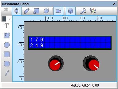
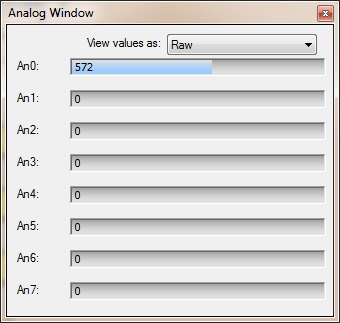
Analogue Inputs Window
The Analogue inputs window available from the View menu allows you to see the values for all of the analogue inputs which are active in your program. They can also be manually altered by dragging the mouse along one of the sliders.
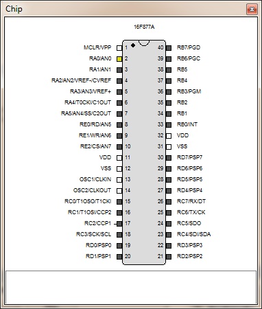
Chip Diagram
Active analogue inputs are highlighted in yellow on the chip diagram.
Scope Window
An ADC based component will automatically add a trace to the data recorder window allowing you to get a view of the analogue data over time during simulation.
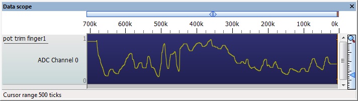
Based on the Scope Traces component property.
Macro reference
GetAverageByte

|
GetAverageByte
|
| Function call to read the ADC as a byte average sample over time
|
 - BYTE - BYTE
|
NumSamples
|
|
|
| - BYTE
|
DelayUs
|
| Number of micro seconds in between taking each sample
|
| - BYTE
|
Return
|
GetAverageInt
|
|
GetAverageInt
|
| Function call to read the ADC as a full width average sample over time
|
| - BYTE
|
NumSamples
|
|
|
| - BYTE
|
DelayUs
|
| Number of micro seconds in between taking each sample
|
 - UINT - UINT
|
Return
|
GetByte
|
|
GetByte
|
| Blocking call to read the ADC as a byte
|
| - BYTE
|
Return
|
GetInt
|
|
GetInt
|
| Blocking call to read the ADC at full bit depth
|
| - UINT
|
Return
|
GetString
|
|
GetString
|
| Reads the ADC as a direct voltage and returns as a string
|
 - STRING - STRING
|
Return
|
GetVoltage
|
|
GetVoltage
|
| Reads the ADC as a direct voltage
|
 - FLOAT - FLOAT
|
Return
|
Property reference

|
Properties
|

|
Connections
|

|
Channel
|
| Analogue Input Channel - Which pin is the analogue input connected to?
|
|
|
Settings
|

|
VRef voltage
|
| Used by the GetVoltage or GetString component macros to take an ADC reading and convert it into a Voltage. +VRef voltage x 10mV Default 500 = 5.0V
|

|
VRef option
|
| Defines what is used as the ADC maximum reference. ADC Range = GND to VRef Voltage VDD - Defines the microcontrollers power supply pin as the max reference, VREF+ Pin - Dedicated pin on the microcontroller to allow for a variable reference voltage.
|
|
|
Conversion speed
|
| Clock setting to select how fast the ADC peripheral will perform an ADC conversion. The FRC setting is based on a RC time base and so will vary with temperature and pressure. Other settings are generally based on divisions of the master clock.
|
|
|
Acquisition cycles
|
| Number of micro seconds to wait for the ADC input to charge before starting the analogue sample.
|
|
|
Bit Depth
|
| Maximum number of digital bits the ADC can sample. 8 bit = ADC range 0 - 255 10 bit = ADC range 0 - 1023 12 bit = ADC range 0 - 4095
|
|
|
Simulation
|

|
Scope Traces
|
| Selects if the scope traces are automatically generated or not
|
Component Source Code
Please click here to download the component source project: FC_Comp_Source_adc_Base.fcfx
Please click here to view the component source code (Beta): FC_Comp_Source_adc_Base.fcfx


