|
|
| Line 16: |
Line 16: |
|
| |
|
| ==Detailed description== | | ==Detailed description== |
| | |
| | |
|
| |
|
|
| |
|
| Line 22: |
Line 24: |
|
| |
|
| ==Examples== | | ==Examples== |
| | |
| | |
|
| |
|
|
| |
|
| Line 200: |
Line 204: |
| |- | | |- |
| | colspan="2" | Sets up the 1-Wire output pin ready for communications. | | | colspan="2" | Sets up the 1-Wire output pin ready for communications. |
| |-
| |
| |-
| |
| | width="10%" align="center" style="border-top: 2px solid #000;" | [[File:Fc9-void-icon.png]] - VOID
| |
| | width="90%" style="border-top: 2px solid #000;" | ''Return''
| |
| |}
| |
|
| |
|
| |
| {| class="wikitable" style="width:60%; background-color:#FFFFFF;"
| |
| |-
| |
| | width="10%" align="center" style="background-color:#D8C9D8;" align="center" | [[File:Fc9-comp-macro.png]]
| |
| | width="90%" style="background-color:#D8C9D8; color:#4B008D;" | '''SetAnalogInput'''
| |
| |-
| |
| | colspan="2" | Sets the state of a single analogue input.
| |
| |-
| |
| |-
| |
| | width="10%" align="center" | [[File:Fc9-u16-icon.png]] - UINT
| |
| | width="90%" | Address
| |
| |-
| |
| | colspan="2" | Coil Address
| |
| |-
| |
| | width="10%" align="center" | [[File:Fc9-u16-icon.png]] - UINT
| |
| | width="90%" | Value
| |
| |-
| |
| | colspan="2" | Analogue Value range 0 - 65535
| |
| |-
| |
| | width="10%" align="center" style="border-top: 2px solid #000;" | [[File:Fc9-void-icon.png]] - VOID
| |
| | width="90%" style="border-top: 2px solid #000;" | ''Return''
| |
| |}
| |
|
| |
|
| |
| {| class="wikitable" style="width:60%; background-color:#FFFFFF;"
| |
| |-
| |
| | width="10%" align="center" style="background-color:#D8C9D8;" align="center" | [[File:Fc9-comp-macro.png]]
| |
| | width="90%" style="background-color:#D8C9D8; color:#4B008D;" | '''Initialise'''
| |
| |-
| |
| | colspan="2" | Starts up the UART to allow communications and initialises the states of the various Modbus Coils, Inputs and Registers to 0.
| |
| |-
| |
| |-
| |
| | width="10%" align="center" style="border-top: 2px solid #000;" | [[File:Fc9-void-icon.png]] - VOID
| |
| | width="90%" style="border-top: 2px solid #000;" | ''Return''
| |
| |}
| |
|
| |
|
| |
| {| class="wikitable" style="width:60%; background-color:#FFFFFF;"
| |
| |-
| |
| | width="10%" align="center" style="background-color:#D8C9D8;" align="center" | [[File:Fc9-comp-macro.png]]
| |
| | width="90%" style="background-color:#D8C9D8; color:#4B008D;" | '''Initialise'''
| |
| |-
| |
| | colspan="2" | Initialises the MIDI component and sets up the UART.
| |
| |-
| |
| |-
| |
| | width="10%" align="center" style="border-top: 2px solid #000;" | [[File:Fc9-void-icon.png]] - VOID
| |
| | width="90%" style="border-top: 2px solid #000;" | ''Return''
| |
| |}
| |
|
| |
|
| |
| {| class="wikitable" style="width:60%; background-color:#FFFFFF;"
| |
| |-
| |
| | width="10%" align="center" style="background-color:#D8C9D8;" align="center" | [[File:Fc9-comp-macro.png]]
| |
| | width="90%" style="background-color:#D8C9D8; color:#4B008D;" | '''CommsBaud'''
| |
| |-
| |
| | colspan="2" | Sets the Baud rate of the alt communications channel
| |
| |-
| |
| |-
| |
| | width="10%" align="center" | [[File:Fc9-u8-icon.png]] - BYTE
| |
| | width="90%" | Baud
| |
| |-
| |
| | colspan="2" | Range: 0-7 : 0=1200 / 7=115200
| |
| |-
| |
| | width="10%" align="center" style="border-top: 2px solid #000;" | [[File:Fc9-void-icon.png]] - VOID
| |
| | width="90%" style="border-top: 2px solid #000;" | ''Return''
| |
| |}
| |
|
| |
|
| |
| {| class="wikitable" style="width:60%; background-color:#FFFFFF;"
| |
| |-
| |
| | width="10%" align="center" style="background-color:#D8C9D8;" align="center" | [[File:Fc9-comp-macro.png]]
| |
| | width="90%" style="background-color:#D8C9D8; color:#4B008D;" | '''LCDOptions'''
| |
| |-
| |
| | colspan="2" | Controls some of the LCD options
| |
| |-
| |
| |-
| |
| | width="10%" align="center" | [[File:Fc9-u8-icon.png]] - BYTE
| |
| | width="90%" | Foreground
| |
| |-
| |
| | colspan="2" | Range: 0-1
| |
| |-
| |
| | width="10%" align="center" | [[File:Fc9-u8-icon.png]] - BYTE
| |
| | width="90%" | Background
| |
| |-
| |
| | colspan="2" | Range: 0-1
| |
| |-
| |
| | width="10%" align="center" | [[File:Fc9-u8-icon.png]] - BYTE
| |
| | width="90%" | Transparent
| |
| |-
| |
| | colspan="2" | Range: 0-1
| |
| |-
| |
| | width="10%" align="center" style="border-top: 2px solid #000;" | [[File:Fc9-void-icon.png]] - VOID
| |
| | width="90%" style="border-top: 2px solid #000;" | ''Return''
| |
| |}
| |
|
| |
|
| |
| {| class="wikitable" style="width:60%; background-color:#FFFFFF;"
| |
| |-
| |
| | width="10%" align="center" style="background-color:#D8C9D8;" align="center" | [[File:Fc9-comp-macro.png]]
| |
| | width="90%" style="background-color:#D8C9D8; color:#4B008D;" | '''LCDVerbose'''
| |
| |-
| |
| | colspan="2" | Controls the Verbose mode. When enabled the LCD automatically displays an account of the incoming API commands and parameters. When switched off the LCD is free for the user to control as required.
| |
| |-
| |
| |-
| |
| | width="10%" align="center" | [[File:Fc9-u8-icon.png]] - BYTE
| |
| | width="90%" | Mode
| |
| |-
| |
| | colspan="2" | Range: 0-1 : 0=Off or User Mode / 1=API Verbose Mode
| |
| |-
| |
| | width="10%" align="center" style="border-top: 2px solid #000;" | [[File:Fc9-void-icon.png]] - VOID
| |
| | width="90%" style="border-top: 2px solid #000;" | ''Return''
| |
| |}
| |
|
| |
|
| |
| {| class="wikitable" style="width:60%; background-color:#FFFFFF;"
| |
| |-
| |
| | width="10%" align="center" style="background-color:#D8C9D8;" align="center" | [[File:Fc9-comp-macro.png]]
| |
| | width="90%" style="background-color:#D8C9D8; color:#4B008D;" | '''ReadDigitalInput'''
| |
| |-
| |
| | colspan="2" | Reads a single digital input.
| |
| |-
| |
| |-
| |
| | width="10%" align="center" | [[File:Fc9-u8-icon.png]] - BYTE
| |
| | width="90%" | Channel
| |
| |-
| |
| | colspan="2" |
| |
| |-
| |
| | width="10%" align="center" style="border-top: 2px solid #000;" | [[File:Fc9-u8-icon.png]] - BYTE
| |
| | width="90%" style="border-top: 2px solid #000;" | ''Return''
| |
| |}
| |
|
| |
|
| |
| {| class="wikitable" style="width:60%; background-color:#FFFFFF;"
| |
| |-
| |
| | width="10%" align="center" style="background-color:#D8C9D8;" align="center" | [[File:Fc9-comp-macro.png]]
| |
| | width="90%" style="background-color:#D8C9D8; color:#4B008D;" | '''PWMConfig'''
| |
| |-
| |
| | colspan="2" | Sets the PWM configuration. Channel = 0 - 1 : 0 = EN_AB, A, B / 1 = EN_CD, C, D Period = 0 - 65535 Scaler = 0 - 3 : 0=1:1 1=1:8 2=1:64 3=1:256
| |
| |-
| |
| |-
| |
| | width="10%" align="center" | [[File:Fc9-u8-icon.png]] - BYTE
| |
| | width="90%" | Channel
| |
| |-
| |
| | colspan="2" | Range 0-1
| |
| |-
| |
| | width="10%" align="center" | [[File:Fc9-u16-icon.png]] - UINT
| |
| | width="90%" | Period
| |
| |-
| |
| | colspan="2" | Range: 0-65535
| |
| |-
| |
| | width="10%" align="center" | [[File:Fc9-u8-icon.png]] - BYTE
| |
| | width="90%" | Scaler
| |
| |-
| |
| | colspan="2" | Range: 0-3
| |
| |-
| |
| | width="10%" align="center" style="border-top: 2px solid #000;" | [[File:Fc9-void-icon.png]] - VOID
| |
| | width="90%" style="border-top: 2px solid #000;" | ''Return''
| |
| |}
| |
|
| |
|
| |
| {| class="wikitable" style="width:60%; background-color:#FFFFFF;"
| |
| |-
| |
| | width="10%" align="center" style="background-color:#D8C9D8;" align="center" | [[File:Fc9-comp-macro.png]]
| |
| | width="90%" style="background-color:#D8C9D8; color:#4B008D;" | '''PWMEnable'''
| |
| |-
| |
| | colspan="2" | Allows pulse width modulated transistor outputs to be switched on or off. Bit 0 = Enable AB Bit 1 = A / Bit 2 = B Bit 3 = C / Bit 4 = D Bit 5 = Enable CD
| |
| |-
| |
| |-
| |
| | width="10%" align="center" | [[File:Fc9-u8-icon.png]] - BYTE
| |
| | width="90%" | EnableMask
| |
| |-
| |
| | colspan="2" | Range 0-63 or 0b00000 to 0b111111
| |
| |-
| |
| | width="10%" align="center" style="border-top: 2px solid #000;" | [[File:Fc9-void-icon.png]] - VOID
| |
| | width="90%" style="border-top: 2px solid #000;" | ''Return''
| |
| |}
| |
|
| |
|
| |
| {| class="wikitable" style="width:60%; background-color:#FFFFFF;"
| |
| |-
| |
| | width="10%" align="center" style="background-color:#D8C9D8;" align="center" | [[File:Fc9-comp-macro.png]]
| |
| | width="90%" style="background-color:#D8C9D8; color:#4B008D;" | '''PWMDuty'''
| |
| |-
| |
| | colspan="2" | Sets a single PWM channel duty. Channel = 0 - 5 : 0=EN_AB, 1=A, 2=B, 3=C, 4=D, 5=EN_CD Duty = 0 - 65535
| |
| |-
| |
| |-
| |
| | width="10%" align="center" | [[File:Fc9-u8-icon.png]] - BYTE
| |
| | width="90%" | Channel
| |
| |-
| |
| | colspan="2" | Range 0-5
| |
| |-
| |
| | width="10%" align="center" | [[File:Fc9-u16-icon.png]] - UINT
| |
| | width="90%" | Duty
| |
| |-
| |
| | colspan="2" |
| |
| |-
| |
| | width="10%" align="center" style="border-top: 2px solid #000;" | [[File:Fc9-void-icon.png]] - VOID
| |
| | width="90%" style="border-top: 2px solid #000;" | ''Return''
| |
| |}
| |
|
| |
|
| |
| {| class="wikitable" style="width:60%; background-color:#FFFFFF;"
| |
| |-
| |
| | width="10%" align="center" style="background-color:#D8C9D8;" align="center" | [[File:Fc9-comp-macro.png]]
| |
| | width="90%" style="background-color:#D8C9D8; color:#4B008D;" | '''LCDCursor'''
| |
| |-
| |
| | colspan="2" | Sets the cursor position for the MIAC display
| |
| |-
| |
| |-
| |
| | width="10%" align="center" | [[File:Fc9-u8-icon.png]] - BYTE
| |
| | width="90%" | X
| |
| |-
| |
| | colspan="2" | Range: 0-21
| |
| |-
| |
| | width="10%" align="center" | [[File:Fc9-u8-icon.png]] - BYTE
| |
| | width="90%" | Y
| |
| |-
| |
| | colspan="2" | Range: 0-4
| |
| |-
| |
| | width="10%" align="center" style="border-top: 2px solid #000;" | [[File:Fc9-void-icon.png]] - VOID
| |
| | width="90%" style="border-top: 2px solid #000;" | ''Return''
| |
| |}
| |
|
| |
|
| |
| {| class="wikitable" style="width:60%; background-color:#FFFFFF;"
| |
| |-
| |
| | width="10%" align="center" style="background-color:#D8C9D8;" align="center" | [[File:Fc9-comp-macro.png]]
| |
| | width="90%" style="background-color:#D8C9D8; color:#4B008D;" | '''WriteTran'''
| |
| |-
| |
| | colspan="2" | Allows a single transistor output to be switched on or off.
| |
| |-
| |
| |-
| |
| | width="10%" align="center" | [[File:Fc9-u8-icon.png]] - BYTE
| |
| | width="90%" | Channel
| |
| |-
| |
| | colspan="2" | Range 1-4
| |
| |-
| |
| | width="10%" align="center" | [[File:Fc9-u8-icon.png]] - BYTE
| |
| | width="90%" | Value
| |
| |-
| |
| | colspan="2" | 0 = Off, 1 = On
| |
| |-
| |
| | width="10%" align="center" style="border-top: 2px solid #000;" | [[File:Fc9-void-icon.png]] - VOID
| |
| | width="90%" style="border-top: 2px solid #000;" | ''Return''
| |
| |}
| |
|
| |
|
| |
| {| class="wikitable" style="width:60%; background-color:#FFFFFF;"
| |
| |-
| |
| | width="10%" align="center" style="background-color:#D8C9D8;" align="center" | [[File:Fc9-comp-macro.png]]
| |
| | width="90%" style="background-color:#D8C9D8; color:#4B008D;" | '''Initialise'''
| |
| |-
| |
| | colspan="2" |
| |
| |-
| |
| |-
| |
| | width="10%" align="center" style="border-top: 2px solid #000;" | [[File:Fc9-void-icon.png]] - VOID
| |
| | width="90%" style="border-top: 2px solid #000;" | ''Return''
| |
| |}
| |
|
| |
|
| |
| {| class="wikitable" style="width:60%; background-color:#FFFFFF;"
| |
| |-
| |
| | width="10%" align="center" style="background-color:#D8C9D8;" align="center" | [[File:Fc9-comp-macro.png]]
| |
| | width="90%" style="background-color:#D8C9D8; color:#4B008D;" | '''LCDClear'''
| |
| |-
| |
| | colspan="2" | Clears the MIAC display
| |
| |-
| |
| |-
| |
| | width="10%" align="center" style="border-top: 2px solid #000;" | [[File:Fc9-void-icon.png]] - VOID
| |
| | width="90%" style="border-top: 2px solid #000;" | ''Return''
| |
| |}
| |
|
| |
|
| |
| {| class="wikitable" style="width:60%; background-color:#FFFFFF;"
| |
| |-
| |
| | width="10%" align="center" style="background-color:#D8C9D8;" align="center" | [[File:Fc9-comp-macro.png]]
| |
| | width="90%" style="background-color:#D8C9D8; color:#4B008D;" | '''LCDClear'''
| |
| |-
| |
| | colspan="2" | Clears the LCD
| |
| |- | | |- |
| |- | | |- |
| Author
|
Matrix Ltd
|
| Version
|
1.4
|
| Category
|
Comms: Interface
|
One Wire component
Low level routines for controlling or interacting with a standard one wire interface.
Detailed description
No detailed description exists yet for this component
Examples
Device Scanning
To get started with one wire devices it is often useful to collect the unique device serial number for each and every one wire device you are going to connect to your bus.
For example if you have a bus with two temperature sensors connected it is useful to know which sensor is which. Sensor A is monitoring temperature A and sensor B is monitoring temperature B. The only way to tell which is which is to use the serial number.
Here is a program that scans for devices on a one wire bus and outputs the device count and serial numbers using a LCD.
 One Wire Device Scan LCD
Here is the same program but this time the device count and serial numbers are output using a UART such as on an Arduino or ESP32.
One Wire Device Scan Serial
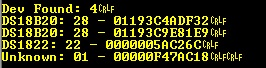
To use the examples simply connect a single device to the one wire bus and make a note of the reported serial number.
This serial number can then be entered into the specific one wire component and used to ensure you are communicating with the device you think you are.
A pull up resistor of between 1K and 10K is required between the data I/O pin and VCC.
Further Examples
The One Wire component is a key building block required by a number of other components. Some of which are included below.
Downloadable macro reference

|
ReceiveByte
|
| Receives a byte from the one wire bus a bit at a time
|
 - BYTE - BYTE
|
Return
|
|
|
TransmitByte
|
| Transmit a byte to the one wire bus a bit at a time
|
| - BYTE
|
Command
|
|
|
 - VOID - VOID
|
Return
|
|
|
SkipROM
|
| Performs a bus reset and the sends the SkipROM command byte
|
| - VOID
|
Return
|
|
|
BusReset
|
| Issue a 'ping' on the bus. If there is at least one sensor on the bus then it will generate a presence pulse. Returns 0 if a presense pulse was detected Returns 1 no device was detected
|
| [[File:]] -
|
Return
|
|
|
MatchROM
|
| Performs a reset followed by the MatchROM code and then the 8-bit ROM code.
|
| - BYTE
|
FamilyCode
|
|
|
| - BYTE
|
SerialNumber
|
|
|
| - VOID
|
Return
|
|
|
ScanBus
|
| Scans the one wire bus to detect all connected devices. Returns the number of one wire devices found.
|
| - BYTE
|
Return
|
|
|
GetDeviceCount
|
| Returns the number of devices found by the last ScanBus operation.
|
| - BYTE
|
Return
|
|
|
GetIDByte
|
| Returns byte ectet of the 64-Bit lasered ROM code, 255 on error
|
| - BYTE
|
Device
|
| Device ID - Range: 0 - NumDevices - 1
|
| - BYTE
|
ByteIndex
|
| Index of the data byte. 0=FamilyCode, 1-6=Serial, 7=CRC
|
| - BYTE
|
Return
|
|
|
Initialise
|
| Sets up the 1-Wire output pin ready for communications.
|
| - VOID
|
Return
|
Property reference

|
Properties
|

|
One Wire Pin
|
| I/O pin used to host one wire bus.
|

|
Max Devices
|
| Controls the maximum number of devices that can be detected during a ScanBus. For each additional device we require 8 bytes to store the ROM ID. Default: 8 = 64 Bytes of RAM
|
|
|
6us Nops
|
|
|
|
|
9us Nops
|
|
|
|
|
10us Nops
|
|
|
|
|
Nop Fiddle
|
|
|

|
Connections
|
|
|
Simulations
|

|
API
|
| Lists all the current injector components available on the user's panel
|


 - BYTE
 - VOID


