Difference between revisions of "Component: Device Helper (Matrix Tools)"
From Flowcode Help
Jump to navigationJump to search| Line 15: | Line 15: | ||
A purely cosmetic component for viewing the details specific to your current selected target microcontroller. Lists stats like ADC resolution, ADC channels, UARTs, SPI, PWM, RAM, ROM etc | A purely cosmetic component for viewing the details specific to your current selected target microcontroller. Lists stats like ADC resolution, ADC channels, UARTs, SPI, PWM, RAM, ROM etc | ||
| − | ==Component | + | ==Component Source Code== |
| − | + | Please click here for the component source code: [https://www.flowcode.co.uk/wikicopy/componentsource/FC_Comp_Source_Device_Helper.fcfx FC_Comp_Source_Device_Helper.fcfx] | |
==Detailed description== | ==Detailed description== | ||
| + | |||
| + | |||
| Line 32: | Line 34: | ||
==Examples== | ==Examples== | ||
| + | |||
| + | |||
| Line 57: | Line 61: | ||
| width="10%" align="center" style="background-color:#D8C9D8;" | [[File:Fc9-prop-icon.png]] | | width="10%" align="center" style="background-color:#D8C9D8;" | [[File:Fc9-prop-icon.png]] | ||
| width="90%" style="background-color:#D8C9D8; color:#4B008D;" | '''Properties''' | | width="90%" style="background-color:#D8C9D8; color:#4B008D;" | '''Properties''' | ||
| + | |- | ||
| + | |- | ||
| + | | width="10%" align="center" style="background-color:#EAE1EA;" | [[File:Fc9-conn-icon.png]] | ||
| + | | width="90%" style="background-color:#EAE1EA; color:#4B008D;" | Device | ||
|- | |- | ||
|- | |- | ||
| Line 78: | Line 86: | ||
|- | |- | ||
| colspan="2" | Million Instructions Per Second (MIPS) Number of complete instruction cycles per second based on the max clock speed and instructions per clock divided by 1 million. Note that some instructions such as decisions can take multiple instructions to complete. | | colspan="2" | Million Instructions Per Second (MIPS) Number of complete instruction cycles per second based on the max clock speed and instructions per clock divided by 1 million. Note that some instructions such as decisions can take multiple instructions to complete. | ||
| + | |- | ||
| + | | width="10%" align="center" style="background-color:#EAE1EA;" | [[File:Fc9-conn-icon.png]] | ||
| + | | width="90%" style="background-color:#EAE1EA; color:#4B008D;" | Memory | ||
| + | |- | ||
|- | |- | ||
| width="10%" align="center" | [[File:Fc9-type-21-icon.png]] | | width="10%" align="center" | [[File:Fc9-type-21-icon.png]] | ||
| Line 93: | Line 105: | ||
|- | |- | ||
| colspan="2" | Number of bytes available for EEPROM storage. EEPROM - Electrically Erasable Programmable Read Only Memory - Contains user data that can persist when the power is removed | | colspan="2" | Number of bytes available for EEPROM storage. EEPROM - Electrically Erasable Programmable Read Only Memory - Contains user data that can persist when the power is removed | ||
| + | |- | ||
| + | | width="10%" align="center" style="background-color:#EAE1EA;" | [[File:Fc9-conn-icon.png]] | ||
| + | | width="90%" style="background-color:#EAE1EA; color:#4B008D;" | Analogue | ||
| + | |- | ||
|- | |- | ||
| width="10%" align="center" | [[File:Fc9-type-21-icon.png]] | | width="10%" align="center" | [[File:Fc9-type-21-icon.png]] | ||
| Line 113: | Line 129: | ||
|- | |- | ||
| colspan="2" | Number of pins capable of outputting an analogue voltage. | | colspan="2" | Number of pins capable of outputting an analogue voltage. | ||
| + | |- | ||
| + | | width="10%" align="center" style="background-color:#EAE1EA;" | [[File:Fc9-conn-icon.png]] | ||
| + | | width="90%" style="background-color:#EAE1EA; color:#4B008D;" | Digital / Peripheral | ||
| + | |- | ||
|- | |- | ||
| width="10%" align="center" | [[File:Fc9-type-21-icon.png]] | | width="10%" align="center" | [[File:Fc9-type-21-icon.png]] | ||
| Line 158: | Line 178: | ||
|- | |- | ||
| colspan="2" | Universal Serial Bus (USB) Used for interconnective communications with high end equipment such as PCs. | | colspan="2" | Universal Serial Bus (USB) Used for interconnective communications with high end equipment such as PCs. | ||
| − | |||
| − | |||
| − | |||
| − | |||
| − | |||
| − | |||
| − | |||
| − | |||
|} | |} | ||
Revision as of 17:45, 9 November 2022
| Author | Matrix TSL |
| Version | 1.1 |
| Category | Matrix Tools |
Contents
Device Helper component
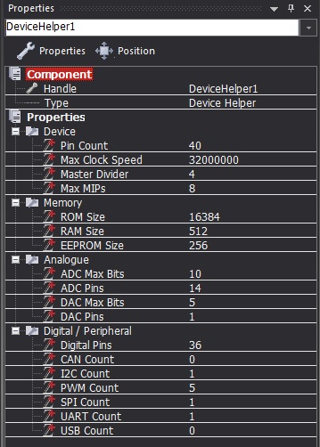
A purely cosmetic component for viewing the details specific to your current selected target microcontroller. Lists stats like ADC resolution, ADC channels, UARTs, SPI, PWM, RAM, ROM etc
Component Source Code
Please click here for the component source code: FC_Comp_Source_Device_Helper.fcfx
Detailed description
No detailed description exists yet for this component
Examples
By simply adding the device helper component to your project and selecting it on the panel you can see all the following statistics regarding your current selected microcontroller in the properties window.
