Component: ADC (AD7680) (Analog Input)
From Flowcode Help
Jump to navigationJump to search| Author | Matrix TSL |
| Version | 1.0 |
| Category | Analog Input |
Contents
ADC (AD7680) component
16-bit external ADC connected to the microcontroller using SPI.
Detailed description
Overview
The AD7680 is a 2.5V to 5.5V SPI compatible, successive approximation analogue to digital converter (ADC).
The reference for the AD7680 is taken internally from VDD
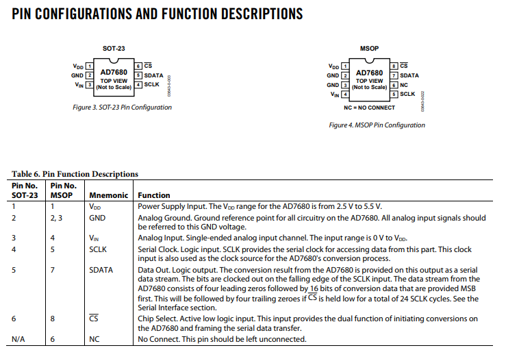
Pin reference from the datasheet:
Examples
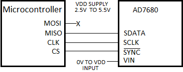
This example reads the voltage on the AD7680 Vin and converts the ADC results into a voltage. For the result to be correct, you must change the Voltage variable to match the supply voltage.
Circuit Diagram
Downloadable macro reference
| SampleADC | |
| Reads the ADC and returns the reading as an unsigned 16-bit value. Range: 0-65535 / 0=0V / 65535=VCC | |
| Return | |
| Initialise | |
| Initialise the SPI bus ready for communications, | |
| Return | |
| NodeWake | |
| Wakes up the local Zigbee module from sleep mode. | |
| Return | |
| ReadATResponse | |
| Reads a single byte from the received AT command response. | |
| idx | |
| Specified the byte index in the buffer. Range 0-15 | |
| Return | |
| ScanBuffer | |
| Returns a binary list of matched identifier names | |
| Compare_Str | |
| Length | |
| Return | |
| SendChar | |
| Transmits a byte value to the Zigbee module. | |
| Byte | |
| Data byte to transmit. Range 0-255 | |
| Return | |
| InitNetwork | |
| Initialises the Zigbee module and attempts to setup or join the network | |
| Return | |
| ConnectToCoordinator | |
| Attempts to connect the data channel to the network coordinator node. | |
| Return | |
| MIAC_Module_GetData | |
| Index | |
| Return | |
| ConnectToName | |
| Attempts to connect the data channel to a named device on the network. | |
| Name | |
| Return | |
| StoreParams | |
| Stores the current register set into the Zigbee module's non volatile memory | |
| Return | |
| EnterCommandMode | |
| Moves from data mode into command mode by sending the special characters | |
| Return | |
| RestartNetwork | |
| Attempts to restart the network | |
| Return | |
| MIAC_Module_Message | |
| CAN_ID | |
| CMD_ID | |
| Return | |
| ConnectToAll | |
| Attempts to connect the data channel to all devices on the network. | |
| Return | |
| ConnectFromLibrary | |
| Attempts to connect the data channel to a known device on the network. | |
| Mode | |
| Device | |
| Return | |
| ConnectToAddress | |
| Attempts to connect the data channel to a specific device address on the network. | |
| Address | |
| Return | |
| GetSignalLevel | |
| Returns the signal strength of the last signal received | |
| Return | |
| ExitCommandMode | |
| Returns from command mode to allow data to be sent and received | |
| Return | |
| MIAC_Module_PushData | |
| Data | |
| Return | |
| ReadAddressFromBuffer | |
| Reads a byte from a 16-bit Zigbee device address | |
| Device | |
| Idx | |
| Return | |
| SendATCommand | |
| Transmits a string of values to the Zigbee module. | |
| Command | |
| Transmits a command to the Zigbee module followed by a carriage return | |
| Return | |
| GetATResponse | |
| Waits for a response from the Zigbee module. If the Logging parameter is set then the response is stored in memory allowing the software to read the reply. | |
| Logging | |
| Return | |
| ReceiveChar | |
| Attempt to receive a byte from the Zigbee module. | |
| nTimeout | |
| Return | |
| ARB4 | |
| Loads the binary-data to an existing arbitrary waveform memory location ARB4. | |
| Waveform | |
| Return | |
| CLKSRRet | |
| Returns the clock source <INT> or <EXT>. | |
| [[File:]] - | Return |
| MODPMDEV | |
| Sets PM waveform deviation to <nrf> degrees. (Lower limit: -360° - Upper limit: 360°). | |
| [[File:]] - | Degrees |
| Sets PM waveform deviation in degrees (-360 - 360). | |
| Return | |
| MSTLOCK | |
| Sends signal to SLAVE generator to get synchronised | |
| Return | |
| HILVL | |
| Sets the amplitude-high-level to <nrf> Volts. (Lower limit: -0.490 V - Upper limit: 5.000 V). | |
| [[File:]] - | HighLevel |
| Sets the amplitude-high-level in Volts(V) (-0.490 V - 5.000 V). | |
| Return | |
| ARB3 | |
| Loads the binary-data to an existing arbitrary waveform memory location ARB3. | |
| Waveform | |
| Return | |
| CALADJ | |
| Adjust the selected calibration value by <nrf> (Lower limit: -100 - Upper limit: 100). | |
| [[File:]] - | Calibrate |
| Adjust the selected calibration value (-100 - 100). | |
| Return | |
| STBRet | |
| Returns the value of the Status Byte Register in <nr1> numeric format. | |
| Return | |
| ARB2 | |
| Loads the binary-data to an existing arbitrary waveform memory location ARB2. | |
| Waveform | |
| Return | |
| EERRet | |
| Query and clear execution error number register. | |
| Return | |
| MODFMSRC | |
| Sets FM waveform source to; 0 INT, 1 = EXT. | |
| [[File:]] - | Source |
| Sets FM waveform source (0 = INT, 1 = EXT). | |
| Return | |
| MODAMFREQ | |
| Sets AM waveform frequency to <nrf> Hz. (Lower limit: 1uHz - Upper limit: 20kHz). | |
| [[File:]] - | Frequency |
| Sets AM waveform frequency in Hertz(Hz) (1uHz - 20kHz). | |
| Return | |
| ESE | |
| Sets the Standard Event Status Enable Register to the value of <nrf>. | |
| Value | |
| Value of register 0-255 | |
| Return | |
| ARB1 | |
| Loads the binary-data to an existing arbitrary waveform memory location ARB1. | |
| Waveform | |
| 16 Bit binary number for arbitrary waveform. | |
| Return | |
| ARB4DEFRet | |
| Returns user specified waveform name, waveform pint interpolation state and waveform length of ARB4. | |
| Return | |
| CLS | |
| Clears status byte register of the interface. | |
| Return | |
| MSTRELOCK | |
| Resynchronises the two generators in MASTER-SLAVE mode. | |
| Return | |
| NOISLVL | |
| Sets the output noise level to <nr1> %. (Lower limit: 0% - Upper limit: 50%) | |
| Percent | |
| Sets the output noise level in percent. (0 - 50) | |
| Return | |
| LOCKMODE | |
| Sets the synchronising mode to; 0 = MASTER, 1 = SLAVE, 2 = INDEP. | |
| Mode | |
| Sets the synchronising mode (0 = MASTER, 1 = SLAVE, 2 = INDEP). | |
| Return | |
| ADDRESSRet | |
| Returns the instruments address | |
| [[File:]] - | Return |
| MODPMSRC | |
| Sets PM waveform source to; 0 INT, 1 = EXT. | |
| [[File:]] - | Source |
| Sets PM waveform source (0 = INT, 1 = EXT). | |
| Return | |
| MODPWMSRC | |
| Sets PWM waveform source to; 0 = INT, 1 = EXT. | |
| [[File:]] - | Source |
| Sets PWM waveform source (0 = INT, 1 = EXT). | |
| Return | |
| MOD | |
| Sets modulation to; 0 = OFF, 1 = AM, 2 = FM, 3 = PM, 4 = FSK, 5 = PWM. | |
| Modulation | |
| Sets modulation (0 = OFF, 1 = AM, 2 = FM, 3 = PM, 4 = FSK, 5 = PWM). | |
| Return | |
| ISTRet | |
| Returns IST local message as defined by IEEE Std. 488.2. The syntax of the response is 0<rmt>, if the local message is false, or 1<rmt>, if the local message is true. | |
| [[File:]] - | Return |
| LRNRet | |
| Returns the complete setup of the instrument as a binary data block | |
| [[File:]] - | Return |
| OPCRet | |
| Query Operation Complete status. The response is always 1<rmt> and will be available immediately the command is executed because all commands are sequential. | |
| [[File:]] - | Return |
| PULSRANGE | |
| Sets PWM waveform source to <1>, <2> or <3>; 1 = 1, 2 = 2, 3 = 3. | |
| Range | |
| Sets the pulse rise and fall range. (1, 2 or 3) | |
| Return | |
| TSTRet | |
| The generator has no self test capability and the response is always 0 <rmt>. | |
| [[File:]] - | Return |
| BSTTRGPOL | |
| Sets the burst trigger slope to; 0 = POS, 1 = NEG. | |
| [[File:]] - | Slope |
| Set the burst trigger slope (0 = POS, 1 = NEG). | |
| Return | |
| ARB3Ret | |
| Returns the binary-data from an existing abbitrary wavefrom memory location. | |
| Return | |
| BSTPHASE | |
| Sets the burst phase to <nrf> degrees. (Lower limit: -360 - Upper limit: 360) | |
| [[File:]] - | Degrees |
| Sets the burst phase in degrees (-360 - 360) | |
| Return | |
| SWPTRGPER | |
| Sets the sweep trigger period to <nrf> seconds | |
| [[File:]] - | Seconds |
| Set the sweep trigger period in seconds. | |
| Return | |
| PULSDLY | |
| Sets the waveform delay to <nrf> sec | |
| [[File:]] - | Sec |
| Return | |
| Initialise | |
| Opens the COM port ready for communications. | |
| Return | |

