Component: I2C Master (Comms: Interface)
| Author | Matrix Ltd. |
| Version | 1.4 |
| Category | Comms: Interface |
Contents
I2C Master component
Generic Two Wire I2C Communications Interface
Detailed description
Overview
The I2C bus is a medium speed communications bus which is usually best suited for talking between devices situated on the same circuit board. Due to the high frequency digital nature of the bus care should be taken to keep tracks as short as possible and as far away as possible from other sources of noise. A typical I2C bus consists of two signals, data and clock. The I2C bus usually consists of a single master device and then one or more slave devices. The master device initiates all the communications and can only communicate with a single device on the bus at a time by sending a unique device address as the first byte.
Each I2C transaction consists of a start and a stop as well as one or more data bytes made up of 8 clock cycles allowing the 8-bits of each byte to be transferred. Each byte send is followed by an Ack (acknowledged) or a Nak (not acknowledged) from the receiving device.
Pull up resistors
The I2C bus usually requires pull up resistors in the range of 4.7K to 10K between the two I2C signals and VCC. Some I2C devices have the pull up resistors built in so as to avoid external components.
The pull up resistors can be useful when interfacing a 5V microcontroller to a 3V3 sensor as the pull up resistor can be connected to 3V3 to eliminate the need for voltage level shifting.
Start / Restart / Stop
The Start, Restart and Stop operations are each states which the bus can be put into using the I2C specification.
Generic Write Transaction
A generic write transaction to a memory device might look something like this:
Start
Send External Device Address Byte (Write mode)
Send Internal Address Byte
Send Data Byte
Stop
Generic Read Transaction
A generic read transaction to a memory device might look something like this:
Start
Send External Device Address Byte (Write mode)
Send Internal Address Byte
Restart
Send External Device Address Byte (Read mode)
Read Data Byte
Stop
Examples
More information on I2C can be found here,
Matrix Flowcode Blog: Simplified communications I2C and SPI
Generic I2C EEPROM
Example file demonstrating how to read and write bytes from a generic I2C EEPROM device.
![]() I2CEEPROM
I2CEEPROM
Simulated I2C devices
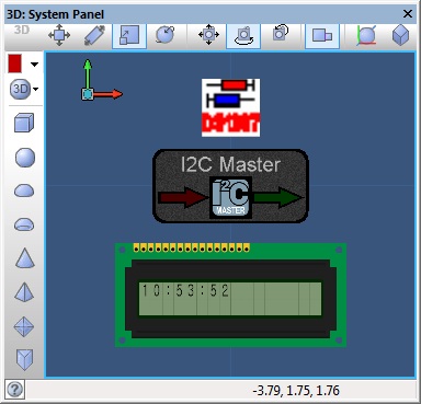
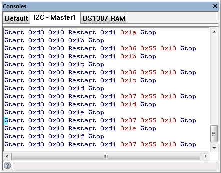
This example uses the I2C master component combined with the DS1307 injector to simulate an I2C communications bus between the target Microcontroller and the virtual DS1307 device.
![]() I2C DS1307 Example
The panel displays the current time from the DS1307 RAM which is populated to match the system time.
I2C DS1307 Example
The panel displays the current time from the DS1307 RAM which is populated to match the system time.
The I2C console shows the communications between the target microcontroller and simulated I2C device.
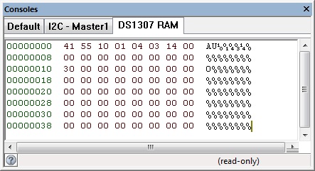
The DS1307 console shows the contents of RAM memory on the simulated I2C device.
Downloadable macro reference
| ReceiveByte | |
| Receives a byte from the I²C bus. | |
| Last | |
| Used to signify the last byte when streaming incoming data. 0=Not last byte, 1=Last Byte | |
| Return | |
| Restart | |
| Outputs a restart condition onto the I²C bus. | |
| Return | |
| Stop | |
| Outputs a stop condition onto the I²C bus. | |
| Return | |
| Transaction_Uninit | |
| Uninitialise the I2C interface | |
| Return | |
| Start | |
| Outputs a start condition onto the I²C bus. | |
| Return | |
| Initialise | |
| Enables the I²C hardware and performs some initialization. Should be called at the start of the program or at least before any of the other I²C functions are called. | |
| Return | |
| CheckNetworkStatus | |
| Returns the state of the GSM network. 0 = Not connected, 1 = connected, 255 = no reply from GSM. | |
| Return | |
| CheckForIncoming | |
| Checks to see if any incoming phone call or SMS message. 0 = Nothing, 1 = Text Received, 2 = Phone Ringing | |
| Return | |
| Initialise | |
| Sets up the GSM module. Returns 0 for OK, 255 for no reply and 254 for command fail. | |
| Return | |


