Component: Grove I2C Motor Driver (Mechatronics)

From Flowcode Help
Revision as of 11:19, 20 October 2023 by Wiki bot (talk | contribs) (Created page with "{| style="width:50%" |- | width="20%" style="color:gray;" | Author | Matrix TSL |- | width="20%" style="color:gray;" | Version | 1.0 |- | width="20%" style="color:gray...")
(diff) ← Older revision | Latest revision (diff) | Newer revision → (diff)
Jump to navigationJump to search
Author Matrix TSL
Version 1.0
Category Mechatronics


Grove I2C Motor Driver component

A grove board based around the L298P motor driver IC allowing control of two DC motors or a single stepper motor.

Component Source Code

Please click here to download the component source project: FC_Comp_Source_Grove_I2C_Motor_Driver.fcfx

Please click here to view the component source code (Beta): FC_Comp_Source_Grove_I2C_Motor_Driver.fcfx

Detailed description

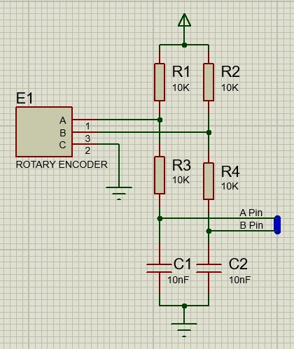
Mechanical encoders can be a bit electrically noisy when switching and so to have reliable operation it is recommended to have a simple filter as shown here.

EncoderCircuit.jpg

Examples

Polling

Example program showing how to use a quadrature encoder component using a polling method. FC6 Icon.png Quad_Encoder_Test

Timer Interrupt Based Polling

Example program showing how to use a quadrature encoder component using a polling method via a timer interrupt. FC6 Icon.png Quad_Encoder_Timer

Interrupt On Change

Example program showing how to use a quadrature encoder component using a interrupt on pin state change interrupt (IOC). FC6 Icon.png Quad_Encoder_IOC


Macro reference

Frequency

Fc9-comp-macro.png Frequency
Set the frequency of PWM (cycle length = 510, system clock = 16MHz) 
Fc9-u8-icon.png - BYTE FrequencySelection
1=31.372 KHz, 2=3.921 KHz, 3=490 Hz, 4=122 Hz, 5=30 Hz 
Fc9-void-icon.png - VOID Return


Initialise

Fc9-comp-macro.png Initialise
Sets up the I2C ready for communications 
Fc9-void-icon.png - VOID Return


Speed

Fc9-comp-macro.png Speed
Sets the speed of a motor. 
Fc9-u8-icon.png - BYTE Motor
1=Motor1 / 2=Motor2 
Fc9-s16-icon.png - INT Speed
Range: -255 to 255 where -255 = Full Backwards, 0=Stop, 255=Full Forwards 
Fc9-void-icon.png - VOID Return


Stop

Fc9-comp-macro.png Stop
Stop one motor 
Fc9-u8-icon.png - BYTE Motor
1 = Motor1 / 2 = Motor2 
Fc9-void-icon.png - VOID Return


Property reference

Fc9-prop-icon.png Properties
Fc9-conn-icon.png Communications
Fc9-type-16-icon.png I2C Address
 
Fc9-type-16-icon.png Channel
Channel selection 
Fc9-type-5-icon.png SDA
Pin used for SDA (data signal) 
Fc9-type-5-icon.png SCL
Pin used for SCL (clock signal) 
Fc9-type-7-icon.png Stop Delay
On older microcontroller devices there is a potential for the I2C hardware channel to lock up if there is not a 10ms delay between an I2C stop event and the next I2C start event. Most modern microcontrollers will not have a problem so this property can be disabled to speed up the I2C communications.  
Fc9-type-16-icon.png Baud Select
Baud rate option selector 
Fc9-type-14-icon.png Baud Rate
Baud rate to be used 
Fc9-type-16-icon.png Default Frequency
 
Fc9-conn-icon.png Simulation
Fc9-type-7-icon.png Scope Traces
Selects if the component pin connections are automatically generated on the data recorder window or not. Yes: Automatically add the component pins to a group on the data recorder which will reflect the sim data during simultion. No: Do not show the pin signals on the data recorder window. 
Fc9-type-7-icon.png Console Data
Selects if the console data is automatically generated or not 
Fc9-type-16-icon.png API
Specifies the API component on the panel to interact with to provide comms simulation.