PC Developer Getting Started Guide
Work in progress
Contents
Introduction
PC Developer allows you to easily create programs to control and monitor devices external to the PC. But it is much more than that. Flowcode PC Developer allows you to create general purpose programs with user interfaces that calculate, plot and display information. It can gather information for from your desk, from inside your building, in your town, and across the world over the internet.
Flowcode PC Developer uses the same programming interface as Flowcode Embedded. So if you know Flowcode you can now easily design Windows apps for your own use or for royalty free distribution to others.
One particular strength is that Flowcode PC Developer contains a large number of communication components that allow you to create distributed control, data gathering and analytical systems so it is particularly good at creating PC Developer like systems using Application Programming Interfaces (API). Support for popular USB, Bluetooth, and Web based hardware platforms like Modbus PLCs, Arduino, Raspberry Pi, Ethernet, ESP32 and other systems are provided.
Getting started
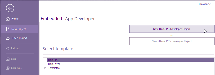
To start web developer, run Flowcode and select NEW PROJECT
Select App Developer tab then select Blank PC then New Blank PC Developer Project
Select File, Save As... and name your project e.g. My First PCD Project. The project file extension will be .fcsx
Creating a basic project with a shape and text
We will need to add the following components to the 2D panel:
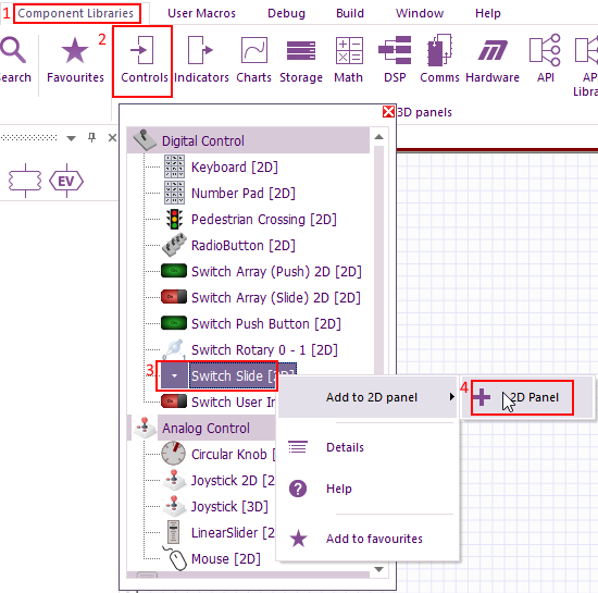
Select Component Libraries from the top menu.
Controls > Digital Controls > SwitchSlide [2D]
Indicators > Digital Indicator > LEDMono [2D]
Creation> "Primitives (2D) > Text
If this is the first time of adding a component to the 2D panel these are the steps for the Switch:
After you have repeated the steps for the other two components, you can tweak the look by using the component properties.
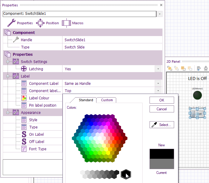
For the Switch and LED indictor, the text can be changed to black for example.
To do that left-click the Switch component on the 2D panel, right-click and select Properties. Double click on the square colour next to Label Colour and select the desired colour e.g. black which is bottom far right.
Select OK.
You will notice that no components should have any pins within properties. That only applies to PC Developer and Web Developer.
Embedded is only Application that has component pins shown (exposed).
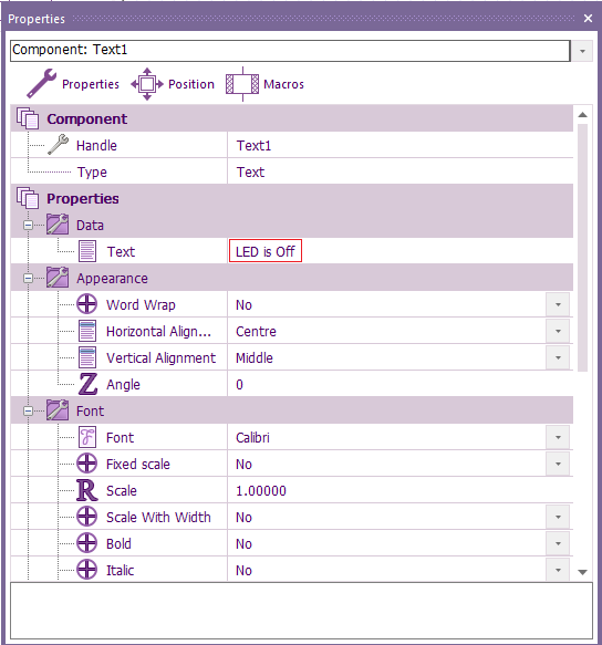
For the Text component Properties, for Data > Text just enter LED is Off
If you would like to align all your components up there are several align and distribute icons near the top of the 2D panel
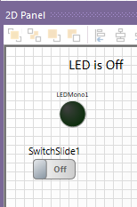
For example, I would like to neaten the components on this 2D panel
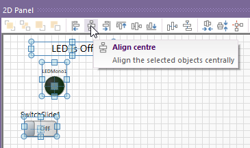
By aligning the three components, so they are all vertically central to each other. First hold the left mouse button down in an area away from all the components.
Keeping the button held move the mouse over all the components so there is a box drawn around them all.
Let go of the mouse button and left click on Align centre
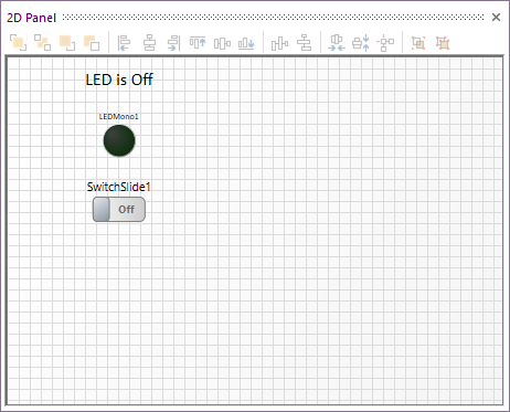
All your components should align like this:
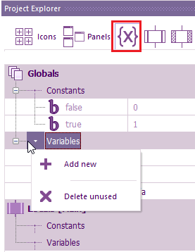
Next, we add all the variables via Project Explorer > Variables icon
For more details on variables, we recommend reading Introduction to microcontroller programming CP4375 which can be found at https://www.matrixtsl.com/learning/
Under Globals, select the down arrow next to Variables > +Add new.
All the variables Array length: is left blank
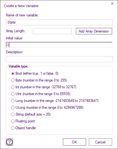
Add a Bool variable State for the Name of new variable: and 0 for the initial value:, Select OK
Add another Bool variable OldState and this time 1 for the initial value:. The reason for the different initial values will be explained later within this getting starting guide.
The last variable to be added is a String variable called Text with no initial value.
The Flowchart code now requires creating.
With PC Developer the code is ran within a forever loop.
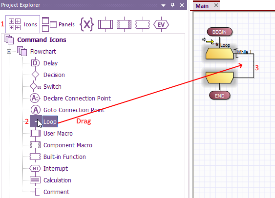
To add the loop within Main select Icons within Project Explorer then select the four + on the left.
Drag a loop on to the Working aera of Main
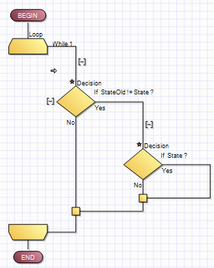
Within the infinite loop drag a Decision Icon, then double click on it.
For the If: Enter StateOld != State
Or you can click down arrow bellow If: and drag the variables to the If: window.
In the Yes branch, drag another Decision icon and for If: just enter State or drag the State variable.
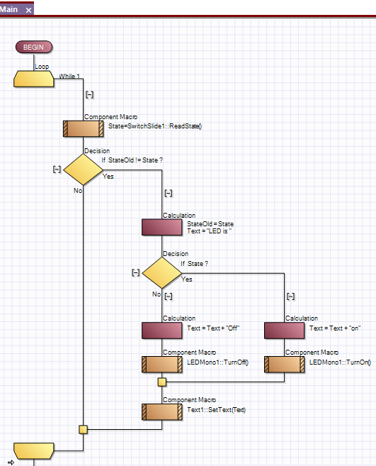
The flowchart working area should look like this:
The red asterisks are changes that have not been saved. As soon as click the save icon they will disappear.
The first decision branch StateOld != State means if the variable StateOld is not equal to the variable State then go down the Yes branch
If the two variables are equal, then go down the No branch.
The If:State just means if State is any value except 0 then go down the Yes branch. If state = 0 then go down the No branch.
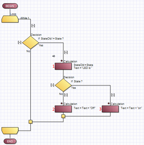
Drag three Calculation icons on the flowchart and double click on each one to enter the equations show below:
1: StateOld = State
   Text = "LED is "
2: Text = Text + "Off"
3: Text = Text + "on"
Select Components icon within the Project Explorer.
Expand all three components to show all the functions by clicking on the +.
Drag a SwitchSlide1 ReadState to just above the first decision branch .it should be just below the While 1 of the Loop.
The switch properties will open and its expecting a Return Value Variable. Enter or drag 'State'
Within the Yes Branch of the If: State decision branch, drag a LEDMono1 TurnON component. It does not matter if placed above or below the Calculation icon.
Within the No Branch of the If: State decision branch, drag a LEDMono1 TurnOff component. It also does not matter if placed above or below the Calculation icon.
The final Icon to add is Text1 SetText which is placed at the very bottom of the first decision branch. For the expression field just below, Expression enter or drag the variable Text
The completed flowchart should look like this:
