Using PC Developer APIs to Control an Arduino
Contents
Introduction
App Developer is an Integrated Development Environment (IDE) for creating Windows-based applications. The software is capable of controlling slave ECIO28/40, Arduino, and ESP32 devices live. It achieves this by using flowcharts instead of text-based languages, thus making controlling simpler and faster.
There is no need to compile and download your program after making changes like you would with an embedded controller.
Since Slave devices are driven in real-time, the changes are instant. App Developer also contains over 120 pre-made component libraries, allowing users to interface slave devices with a host of sensors, inputs and outputs and electro-mechanical components with ease. Despite its simplicity and ease of use, App Developer is a powerful tool allowing users to develop even the most complex of remote hardware interfaces.
What we’ll cover in this guide?
Required firmware for each slave device
Set up app developer for a cleaner workspace.
Changing the colour of the 2D panel.
Set an output on D3 of the Arduino Uno, depending on the2D panel switch setting.
Read and display an analogue input value.
Light an indicator if the input goes above 2.5V.
What is required?
Flowcode V10
Indication of 5V, e.g. 330R – 680R Resistor and LED or multimeter.
Potentiometer 4k7 – 10KΩ
This guide will provide step-by-step instructions on how to develop your first App
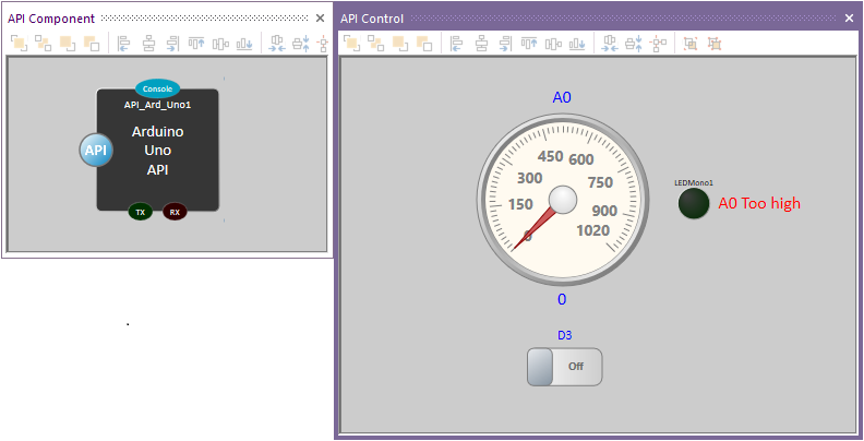
The finished results will look something like this:
First, make sure the slave device, e.g., Arduino UNO, is connected to a PC.
The slave hardware requires the correct slave firmware loaded into it before the App Developer can communicate with the slave device.
Within the wiki search box, search for SCADA Slaves.
Find the slave you will be using, e.g. Component: SCADA (Arduino Uno) (SCADA Slaves)
Select the link and download the SCADA Firmware.
The zip file will contain three files:
I loaded Arduino_Uno_SCADA_Firmware.fcfx file and then compiled to the target device.
If this firmware is not loaded on the slave hardware, UNO, then the APP Developer will not work.
Now for the Ap developer code.
Open Flowcode, select new project, then select App Developer tab.
Expand API arrow then API slave.
Choose the slave device, in this case, Arduino Uno API Slave.
Select New < Arduino Uno API Slave> App Developer Project.
Select File, Save, then a Save As window will open.
As with other windows applications, browse to where you want to save the project and give it a suitable name.
Make sure Flowcode is fully up-to-date.
Help Ribbon (Tab). Library Updates…
Change Files in-use to Full database, select Yes for the warning, then Download
If Flowcode Requires restarting, You can select Reload![]()
Setting an output.
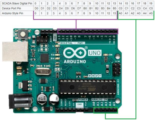
The pin mapping for the Arduino is:
D0 or D1 will not be touched, as the App developer uses them for slave control.
We will connect a basic simulation switch to change digital output D3, which goes to a resistor 330R – 680R.
The Anode of LED connects to the other end of the resistor.
Cathode of LED connects to GND
Analogue A0 is the input to monitor, which goes to the centre pin of a potentiometer.
The other two ends of the potentiometer connect to 5V and GND connections
Ensure the 2D Panel (View Ribbon, 2D Panels) is in view as all the applications will be more than likely developed using it.
Move the already added UNO Scada component out of the way by selecting it and dragging it.
Alternatively, the component can move to a precise location by right-clicking on the component, select properties and Position icon.
Or add another 2D panel as you can have as many 2D panels as you like.
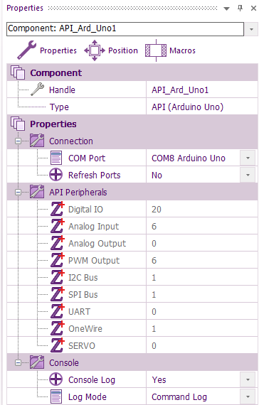
The communications port requires selecting.
It is best to know which the correct port is to use, especially if there are multiple com ports in use.
Within the search of the PC’s taskbar, enter Device Manager.
Expand Ports (Com & LPT) and look for either Ardunio Uno or USB Serial Device (depends on which drivers were used) and remember the Com port number.
If not still got properties window open, right-click anywhere on 2D Panel then select properties.
Make sure Properties is selected and not Position and select the correct port for the Arduino.
If unable to see the correct com port, then try the Refresh port option.
Failing that, use the Reload option mentioned earlier, then the Refresh Ports option.
Select the Uno Scada component on the 2D Panel.
For now, change the Log Mode from Fixed Statistics option to Command log.
The reason for this will be covered when running the App for the first time.
Adding a switch.
Go to the Component Libraries Ribbon, select controls and Left or right-click on the switch, select Add to 2D Panel (or the name of the panel is more than one, or the 2D panel is renamed.
All components added will default to the very centre i.e. X = 0 and Y = 0
Right-click on the switch and select properties.
Enter your desired text for the on/off labels.
If the switch requires resizing, for example, all the label text is not visible. Click on the switch, then click and drag the grab handles to resize.
From the Component Libraries ribbon, Indicators
Add 1 of each of the following components:
On/Off Indicator (Or one of the LEDs and Circular Gauge. From the Component Libraries ribbon, Creation, 2d primitives add Text [2D].
Text is perfect for labels and dynamically changing text on the 2D/3D panels.
My preference is to change Text Gradient to the same as the text colour. Change the border to the ideal size, ignoring text size.
Once you are happy with the size and colour, select the text on the 2D Panel, right-click copy then paste (or ctrl c, ctrl v) so you have two more in the same format.
When happy with the border size, change the text size via Scale if not ideal.
The default colour of the 2D panel is white smoke with a white Gradient, Diagonal Left and showing gridlines.
The background colour could be any colour.
Just select the 2D panel properties and change to any colour. My preference is to have the grid lines off.
In the Circular Gauge, properties change the upper Bound to 1020, Major Tip Step to 10 and Minor Tick Step to 15. For the gauge to remove the decimal point change the label format to %0.0f The goal is to change the size of the static text labels & text and move them to match the image below:
Tip. For perfect alignment of the components.
Select the properties of a component, e.g. Circular gauge.
Make sure Position is selected.
For the X within Top Left, enter a whole number.
There are also Align left, Align right, Align top and Align bottom at the top of the 2D panel.
Do the same thing for the Text labels above and below the Circular gauge
Tip. Set up app developer for a cleaner workspace by docking the 2D panel.
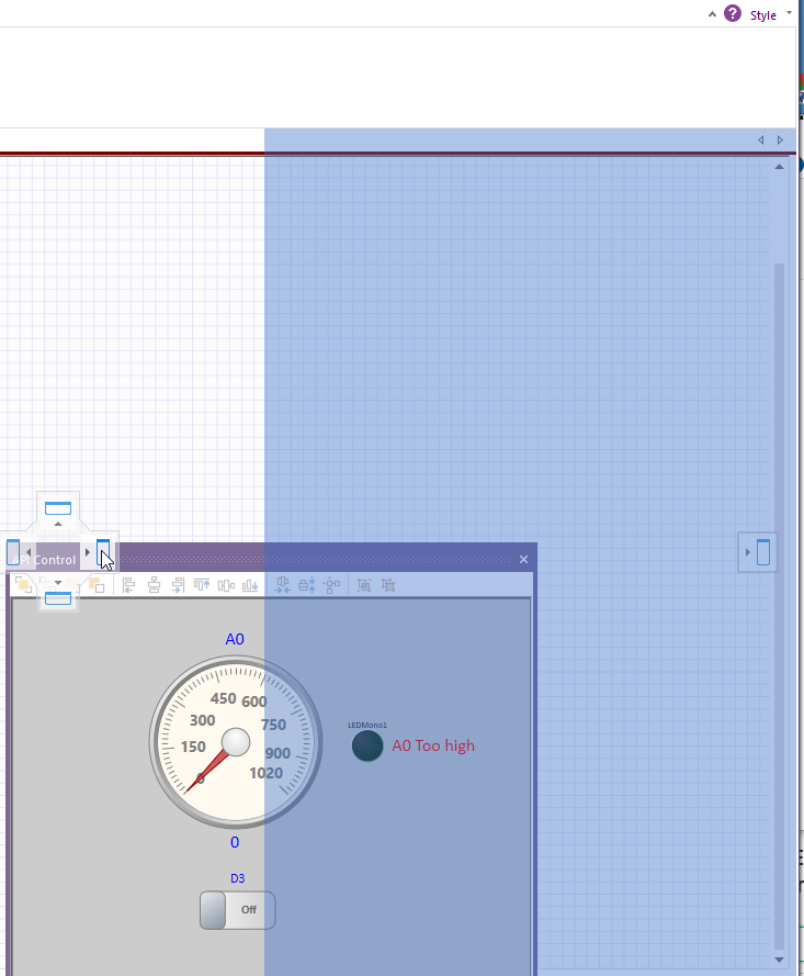
To doc the 2D Panel on the right-hand side
Hold the left mouse button on the title bar of the 2D Panel.
Drag to the middle of the screen, then make sure the 2D Panel and mouse is in line with the right docking icon:
When you see the shadow, you can let go of the mouse.
Programming App Developer
App Developer is very easy to program.
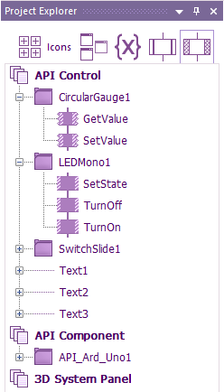
Personally, I like to use Project Explorer (View ribbon)
All components add can be used by selecting:
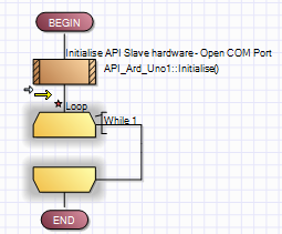
The first thing we need to do is to add a continuous loop within Main. Otherwise, the App will run the routine once and then stop.
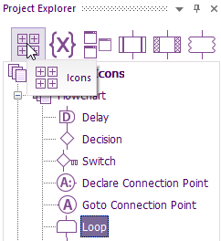
With Command icons selected (or you can choose from Command Icons ribbon), drag a loop
to below SCADA_Ard_Uno1 component.
The red star means the flowchart has not been saved since the last change.
I would recommend saving very regularly by click on the save icon 
Now we can get the switch to control pin D2 on the Arduino.
The state of the switch is read using GetState
The pin D2 state will be set depending on the state of the switch, so a decision component is used to
do that.
Drag a Components icon within the Command Icons to inside the loop, then double left-click on it.
Look down the alphabetical component list for Switch1.
Click on the + to expand and display all the options.
