Using PC Developer APIs to Control an Arduino
Contents
Introduction
PC Developer is an Integrated Development Environment (IDE) for creating Windows-based applications. The software is capable of controlling slave ECIO28/40, Arduino, and ESP32 devices live. It achieves this by using flowcharts instead of text-based languages, thus making controlling simpler and faster.
There is no need to compile and download your program after making changes like you would with an embedded controller.
Since Slave devices are driven in real-time, the changes are instant. PC Developer also contains over 120 pre-made component libraries, allowing users to interface slave devices with a host of sensors, inputs and outputs and electro-mechanical components with ease. Despite its simplicity and ease of use, PC Developer is a powerful tool allowing users to develop even the most complex of remote hardware interfaces.
What we’ll cover in this guide?
Required firmware for each slave device
Set up PC Developer for a cleaner workspace.
Changing the colour of the 2D panel.
Adding an additional 2D panel.
Set an output on D3 of the Arduino Uno, depending on the 2D panel switch setting.
Read and display an analogue input value.
Light an indicator if the input goes above 2.5V.
What is required?
Flowcode V10
Indication of 5V, e.g. 330R – 680R Resistor and LED or multimeter.
Potentiometer 4k7 – 10KΩ
This guide will provide step-by-step instructions on how to develop your first App
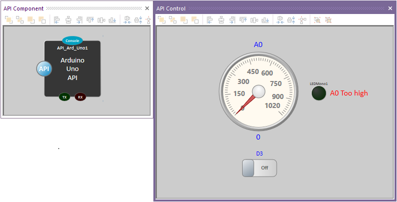
The finished results will look something like this:
First, make sure the slave device, e.g., Arduino UNO, is connected to a PC.
The slave hardware requires the correct slave firmware loaded into it before the PC Developer can communicate with the slave device.
Within the wiki search box, search for SCADA Slaves.
Find the slave you will be using, e.g. Component: SCADA (Arduino Uno) (SCADA Slaves)
Select the link and download the SCADA Firmware.
The zip file will contain three files:
I loaded Arduino_Uno_SCADA_Firmware.fcfx file and then compiled to the target device.
If this firmware is not loaded on the slave hardware, UNO, then the PC Developer will not work.
Now for the Ap developer code.
Open Flowcode, select new project, then select PC Developer tab.
Expand API arrow then API slave.
Choose the slave device, in this case, Arduino Uno API Slave.
Select New < Arduino Uno API Slave> PC Developer Project.
Select File, Save, then a Save As window will open.
As with other windows applications, browse to where you want to save the project and give it a suitable name.
Make sure Flowcode is fully up-to-date.
Help Ribbon (Tab). Library Updates…
Change Files in-use to Full database, select Yes for the warning, then Download
If Flowcode Requires restarting, You can select Reload![]()
Setting an output.
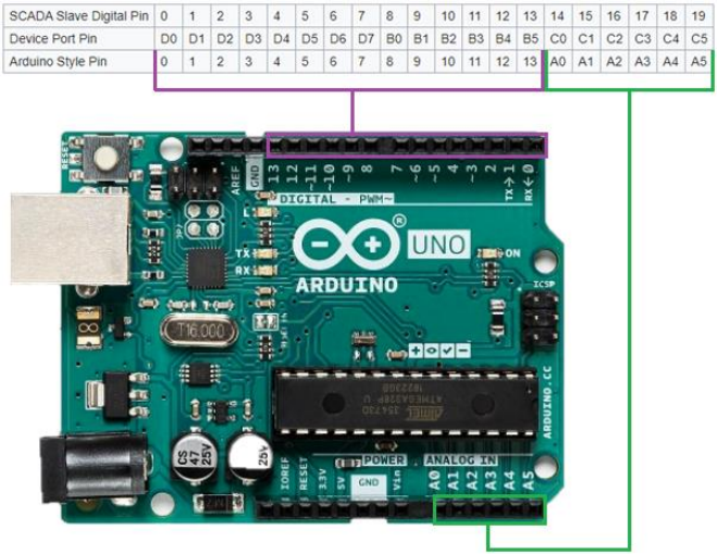
The pin mapping for the Arduino is:
D0 or D1 will not be touched, as the PC Developer uses them for slave control.
We will connect a basic simulation switch to change digital output D3, which goes to a resistor 330R – 680R.
The Anode of LED connects to the other end of the resistor.
Cathode of LED connects to GND
Analogue A0 is the input to monitor, which goes to the centre pin of a potentiometer.
The other two ends of the potentiometer connect to 5V and GND connections
Ensure the 2D Panel (View Ribbon, 2D Panels) is in view as all the applications will be more than likely developed using it.
Move the already added UNO Scada component out of the way by selecting it and dragging it.
Alternatively, the component can move to a precise location by right-clicking on the component, select properties and Position icon.
Or do what I did and add another 2D panel as you can have as many 2D panels as you like.
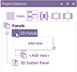
To add additional 2D panels, select the Panels Icon of the project explorer. Left or right-click on the 2D Panels and select Add New
To rename reach 2D panel, right click on the 2D panel to be rennamed and select Rename
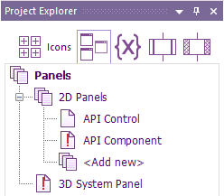
If you see a red exclamation mark,that means the panel is hidden.
If you want it visible then right-click on the panel and select Show.
To move a component to a different panel e.g move API_Ard_Uno1. Select the component and right-click on it and select Move to, then chose the panel to move it to
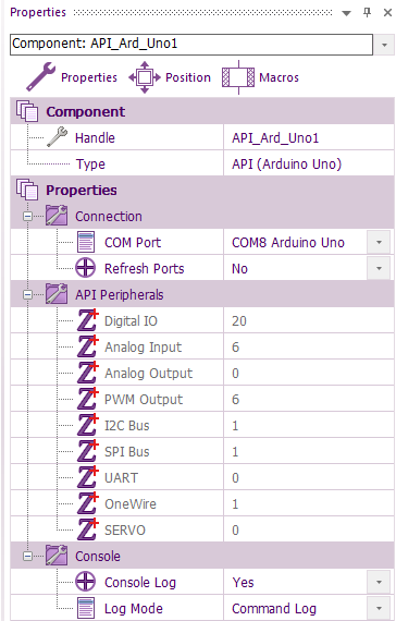
The communications port requires selecting.
It is best to know which the correct port is to use, especially if there are multiple com ports in use.
Within the search of the PC’s taskbar, enter Device Manager.
Expand Ports (Com & LPT) and look for either Ardunio Uno or USB Serial Device (depends on which drivers were used) and remember the Com port number.
If not still got the properties window open, right-click anywhere on 2D panel then select properties.
Make sure Properties is selected and not Position and select the correct port for the Arduino.
If unable to see the correct com port, then try the Refresh port option.
Failing that, use the Reload option mentioned earlier, then the Refresh Ports option.
Select the Uno Scada component on the 2D Panel.
For now, change the Log Mode from Fixed Statistics option to Command log.
The reason for this will be covered when running the App for the first time.
Adding a switch.
Go to the Component Libraries Ribbon, select controls and Left or right-click on the switch, select Add to 2D Panel (or the name of the panel is more than one, or the 2D panel is renamed.
All components added will default to the very centre i.e. X = 0 and Y = 0
Right-click on the switch and select properties.
Enter your desired text for the on/off labels.
Make sure Latching is set to Yes
If the switch requires resizing, for example, all the label text is not visible. Click on the switch, then click and drag the grab handles to resize.
From the Component Libraries ribbon, Indicators
Add 1 of each of the following components:
LEDMono (Or the On/Off Indicator) and Circular Gauge. From the Component Libraries ribbon, Creation, 2d primitives add three lots of Text [2D].
Text is perfect for labels and dynamically changing text on the 2D/3D panels.
My preference is to change Text Gradient to the same as the text colour. Change the border to the ideal size, ignoring text size.
Once you are happy with the size and colour, select the text on the 2D Panel, right-click copy then paste (or ctrl c, ctrl v) so you have two more in the same format.
When happy with the border size, change the text size via Scale if not ideal.
The Text will be used for LEDMono1 text (A0 Too high) = Text2, A0 label = Text1 and ADC value of the CircularGauge1 = Text3.
The default colour of the 2D panel is white smoke with a white Gradient, Diagonal Left and showing gridlines.
The background colour could be any colour.
Just select the 2D panel properties and change to any colour. My preference is to have the grid lines off.
In the Circular Gauge, properties change the upper Bound to 1020, Major Tip Step to 10 and Minor Tick Step to 15. For the gauge to remove the decimal point change the label format to %0.0f The goal is to change the size of the static text labels & text and move them to match the image below:
Tip. For perfect alignment of the components.
Select the properties of a component, e.g. Circular gauge.
Make sure Position is selected.
For the X within Top Left, enter a whole number.
There are also Align left, Align right, Align top and Align bottom at the top of the 2D panel.
Do the same thing for the Text labels above and below the Circular gauge
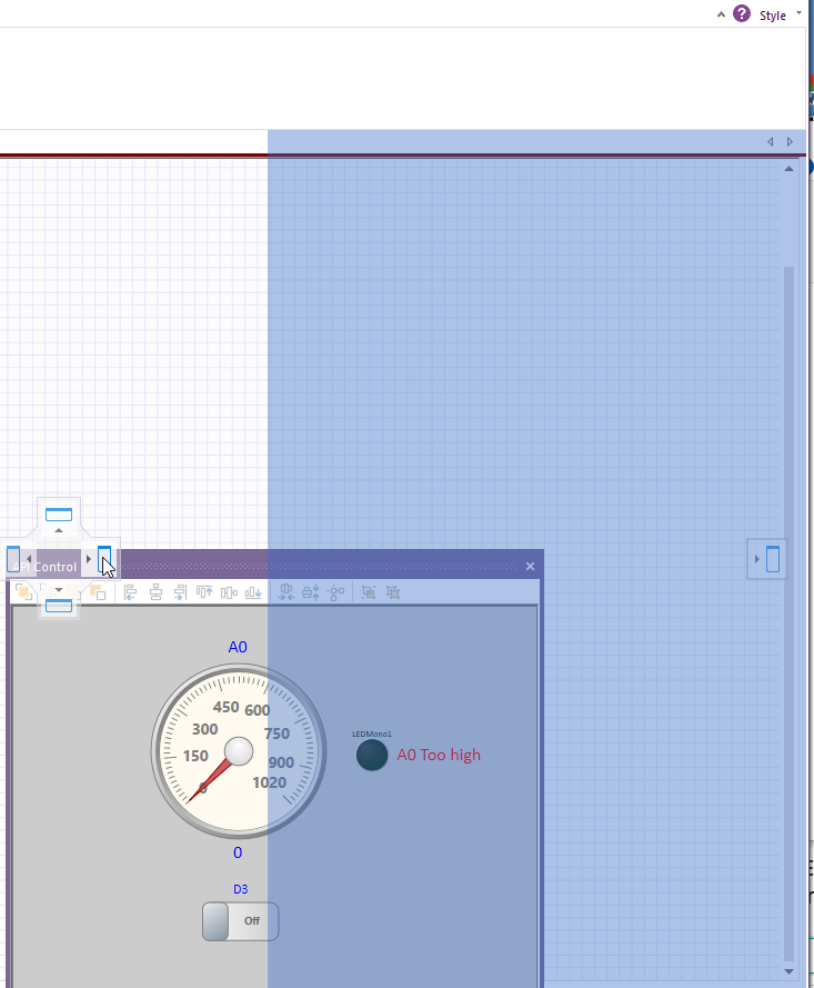
Tip. Set up PC Developer for a cleaner workspace by docking the 2D panel.
To doc the 2D Panel on the right-hand side
Hold the left mouse button on the title bar of the 2D Panel.
Drag to the middle of the screen, then make sure the 2D Panel and mouse is in line with the right docking icon:
When you see the shadow, you can let go of the mouse.
Programming PC Developer
PC Developer is very easy to program.
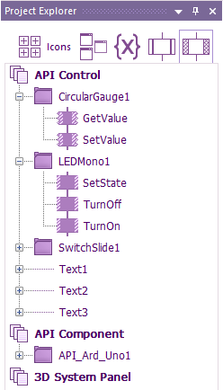
Personally, I like to use Project Explorer (View ribbon)
All components add can be used by selecting:
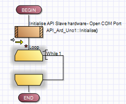
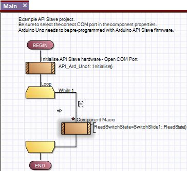
The first thing we need to do is to add a continuous loop within Main. Otherwise, the App will run the routine once and then stop.
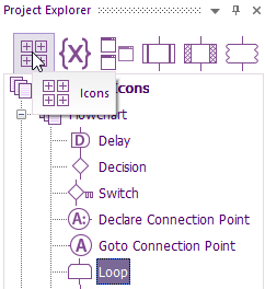
With Command icons selected (or you can choose from Command Icons ribbon), drag a loop
to below SCADA_Ard_Uno1 component.
The red star means the flowchart has not been saved since the last change.
I would recommend saving very regularly by click on the save icon 
Now we can get the switch to control pin D2 on the Arduino.
The state of the switch is read using GetState
The pin D2 state will be set depending on the state of the switch, so a decision component is used to do that.
Drag a Components icon within the Command Icons to inside the loop, then double left-click on it.
Look down the alphabetical component list for Switch1.
Click on the + to expand and display all the options.
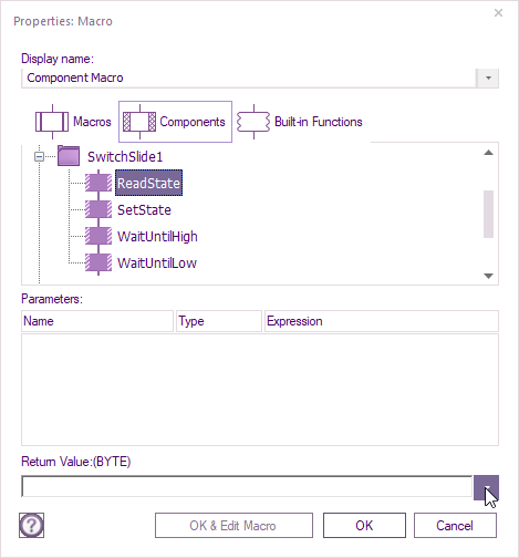
As we are reading the switch state, Select ReadState.
A variable must be used to pass on the state of the switch.
A variable is just a location in memory that can be given a name that can remind us in the future what it is used for, e.g. ReadSwitchState
The variable could either store a string that is just characters, e.g. Hello world Or store a range of numbers depending on the type of the variable used. E.g. a bool which is just 1 or 0, a byte which is 0 to 255.
You will see the rest of the ranges when the first variable is entered.
To enter a variable, click on the down arrow in the return value box:
The window that pops up defaults to global variables.
The difference between global and local is global can be accessed anywhere in the code.
Local variables can only be accessed within the user added macros which is similar to Ardunio functions.
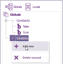
Select the Variables drop-down arrow, then Add new:
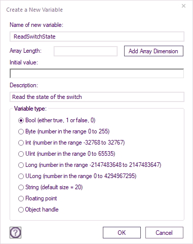
Enter a name that you will know the purpose of, as explained earlier, e.g. ReadSwitchState For good practice, the type of variable to select is the lowest range that will fully meet our requirements.
As the switch only has two states and the return type is a bool, that is the logical type to go for.
For the initial value, if the variable is written before read, then there is no requirement to enter a value.
If the variable is read before written, then to avoid uninitialised value issues, enter a value.
Typing a description could be handy for a memory jogger:
Notice all the different variable types?
Select OK, then double-click the variable to add it to the return value.
Select OK, and then the Switch can now read the state of the pin D2 of the Arduino.
This is what you should see:
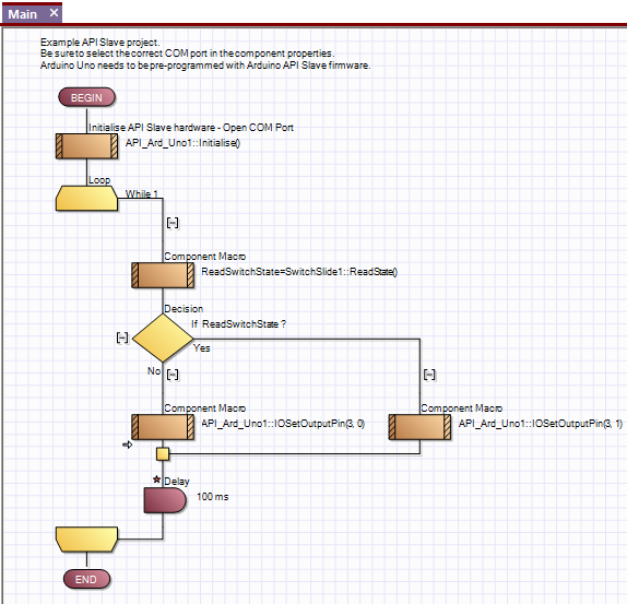
A Decision branch can be used to read the switch state and then acted upon Any Flowchart Command icons like calculations, interrupts, user macros etc., are located in the same place as the loop or in the Command Icons ribbon.
After dragging the Decision to the main loop, just below the switch GetState() icon.
Double click on the decision icon, highlight the 0 (Left click then swipe to the left) just below If: As you did for the switch, click on the down arrow next to the box highlighted with a 0, double click the ReadSwitchState, variable, then OK.
Instead of highlighting, the 0 could be deleted, its personal preference.
The Decision has two branches, Yes for True and No for False.
Within these branches, the actions of the switch status are placed.
For the Yes, that means the switch is on, so Set output D3 to High (+5V)
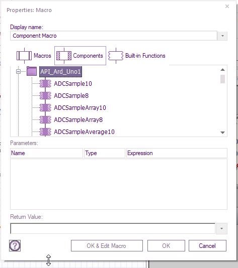
Drag a component macro from Icons & Double click on it.
Expand API_Ard_Uno1.
You might find it easier if you drag the bottom of the properties Macro, so more options can be viewed at once.
Go to the bottom edge, and the cursor will change into a double arrow.
At that point, hold the left button down and drag it to the required size.
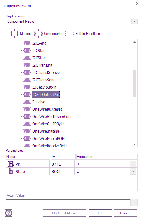
Select IOSetOutputPin then for the Pin expression it’s 3 since Arduino D0 is 0, D1 = 1 etc.
In the State Expression, it’s 1 as that is output high.
If we wanted D3 to be low, then a 0 would be required.
Repeat the steps for the no branch, but enter 0 for the State instead of 1.
Drag a delay from the Command Icons, enter a value of 100ms
Before going any further, we will check that the PC Developer can send commands to the Ardunio slave.
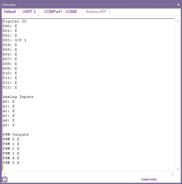
The best way is via the Console. (View ribbon, >_ Consoles).
With the Console in view, select The Arduino API tab.
If you see:
Then the Log Mode properties of the API component require changing Fixed Statistics to Command Log.
A great feature of Flowcode is Code profiling.
Having that enabled from Debug ribbon can make life easier when debugging.
From the Debug ribbon, select Show Code Profiling & have Show Value selected.
Start single-stepping by pressing F8 on your keyboard (or Debug ribbon, click Step Into), and you
should see a red outline around the component icon.
Press F8 after the Initialised icon is accessed, wait a couple of seconds, then press F8 a few more times.
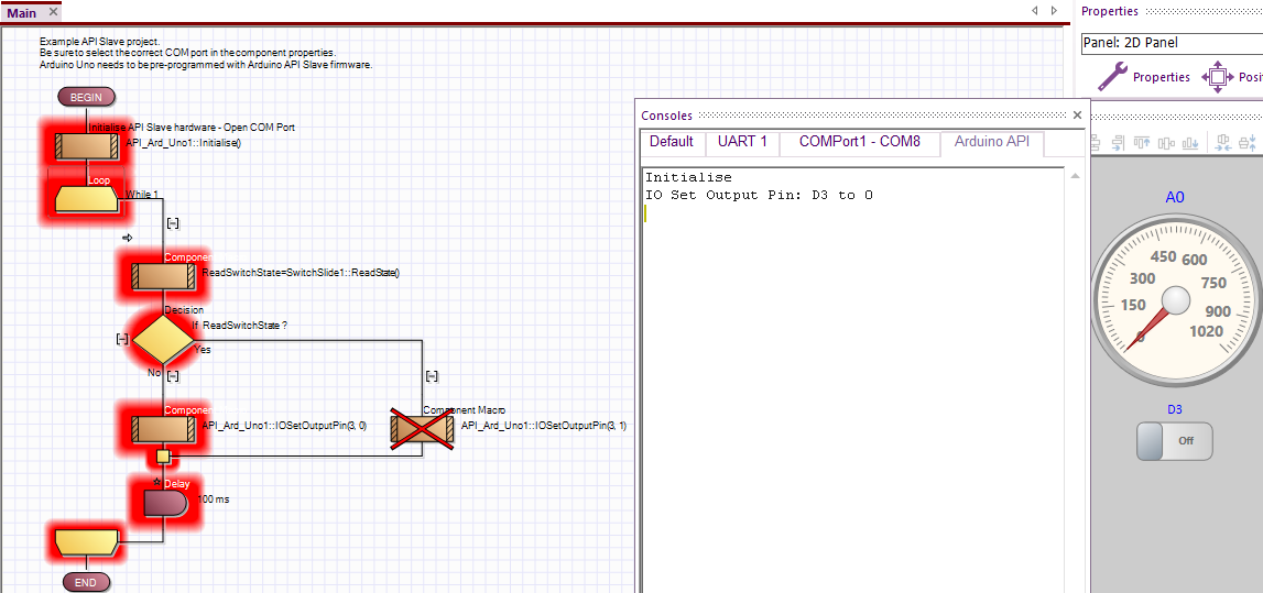
When the first component Icon requires data flowing between PC and Slave, then you can see the data about what is happening on the console window.:
Depending on the switch setting, one of the SetOutputPin component macros will cause communication to occur.
If all is working, you will see IO Set Output Pin: D3 to 0.
If there is a communication issue between PC and target board, then you will see this instead:
If this is the case, then go back to ‘The communications port requires selecting.’ to get communications established.
If there is no Comms Error displayed, then either measure the voltage across D3 & GND, it should be around 0V.
Alternatively, If the resistor and LED are connected, the LED should be off.
With the Code profiling enabled, you will see:
Click on the switch that is on the 2D Panel to change its state from off to on.
Press F8 a few more times then the Yes (true) branched is accessed, changing D3 from 0V to +5V
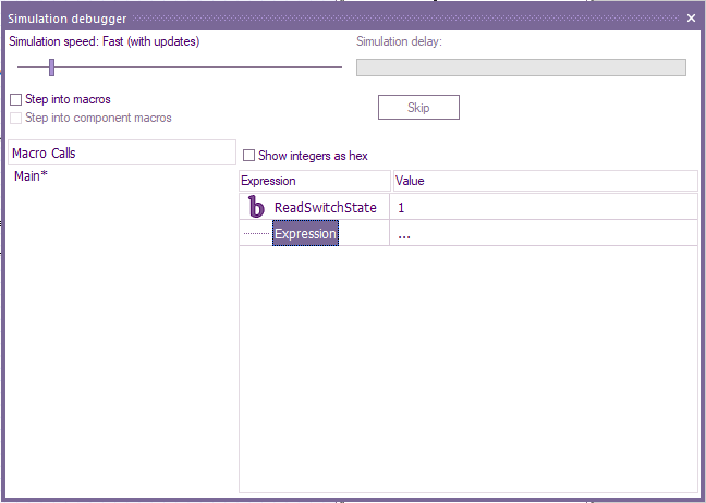
To aid debugging, you can add the ReadSwitchState variable to the Watch window, which only pops up when running a simulation.
Click on the dots next to Expression, select Add Variable.
Scroll down and select ReadSwitchState variable, then OK
Notice the value is 1 because the switch is on, thus setting the ReaSwitchState Variable to 1.
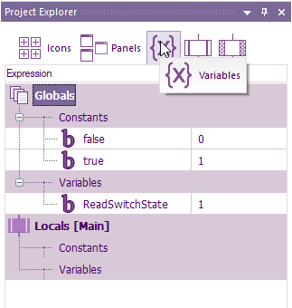
Alternatively, select the variables icon of the project explorer.
You may need to expand the size of the project explorer to get the full variable name within the window,
Reading analogue value. Analogue pins, in the case of Arduino, are labelled A0 to A5.
If read as a byte value, the range will be 0 to 255
If read as a 10bit integer value, the range will be 0 to 1023
With the simulation stopped by clicking on Stop within Debug ribbon
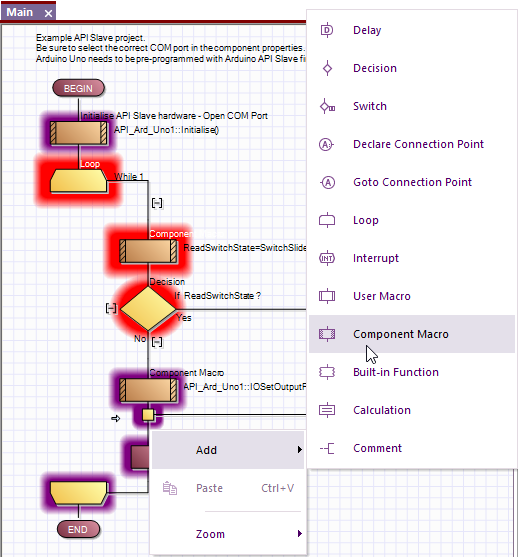
To Read the analogue value of the pin, left-click on the flowchart in the desired place (Just below Decision Icon), you will see a small arrow appear. Right-click on the arrow and select Add, Component Macro:
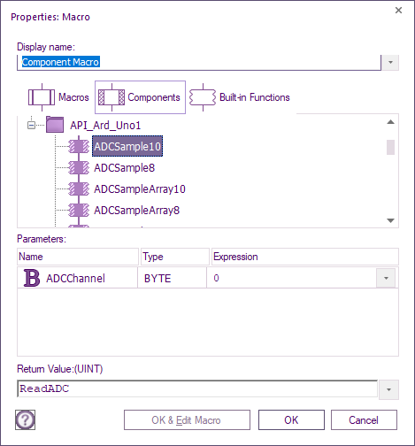
Then double click on the new component icon and click on the + for API_Ard_Uno1,
With a single click, select ADCSample10, then for ADCChannel below, enter 0 for A0.
For the Return value, repeat the same method as creating the variable for the switch (page 9).
The name should be meaningful like ReadADC & the type of variable should cover the range of 0 to 1023.
A signed integer (Int) or unsigned integer (UInt) will be suitable as they the smallest variable range that will hold a maximum value of 1023.
If correct, you will see:
The alternative to left-click on the flowchart is to left-click on Components from the Project Explorer, look for SCADA_Ard_Uno, left-click and drag ADCSample10 to a suitable place below the Decision icon
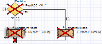
If code profiling is on, you will see a large red X.
Don’t worry about that, as it means the icons have not been accessed during the simulation. It does not mean you made a mistake.
The value of the ReadADC variable will depend on the voltage present across Ardunio A0 and GND 0 = 0V, 1023 = supply voltage going to the Ardunio.
Therefore if you want an indication of when the voltage at A0 is greater than 2.5V Place a Decision icon just below the ADCSample10 and enter ReadADC > 511.
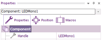
We need to find the LED’s name for the Yes branch by selecting it on the 2D panel Panel and right-click and select properties.
We are only interested in the Handle name:
If you had more than one component of the same type, then the number at the end will be different for each of the components.
There are no variables to add to these type of component icons.
The red star is reminding us that the flowchart requires saving. If the large X is putting you off, then you can turn off Code Profiling until it’s required again. I will do that for the next Flowchart image.
The next component to add is the Circular Gauge. That can go anywhere below the ReadADC component, so long as it’s still within the main loop.
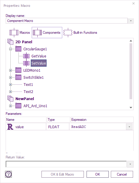
As we are reading a variable and then displaying the variable value SetValue is used.
The variable will be the ReadADC.
It does not matter that the Return value is stating a (FLOAT), but an integer is used instead.
Before the last component can be added, drag a calculation icon from Command Icons to below CircularGuage1.
Double-click on the calculation icon and add another global variable
This time it’s a string, call it TextString. It can be left as (default size=20), select OK
Double-click on the string variable so it goes into the calculations area.
Left-click on the far right of the variable, then add a space then = then another space.
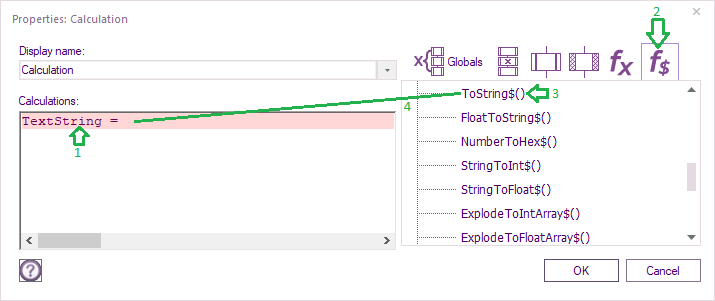
Click on the F$:
which are the string functions.
You will see a list of functions
The function that’s required is ToString$.
Drag that within the calculation icon, after = and space
Add that after the last space.
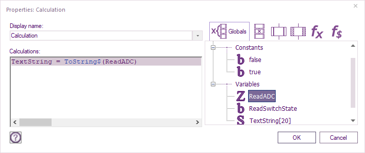
Left-click in between the brackets within the calculation box, then double left-click the ReadADC variable.
The calculation Icon should look like this:
If it does, select OK.
The final component to add is Text3 on my flowchart.
Check yours is also Text3 by Selecting on the Panel, right-clicking and selecting properties as your Text may be a different number.
On the 2D Panel, it’s position was placed at the bottom of the circular gauge.
The purpose is to display the analogue value present on A0 in a numerical form (0 – 1023).
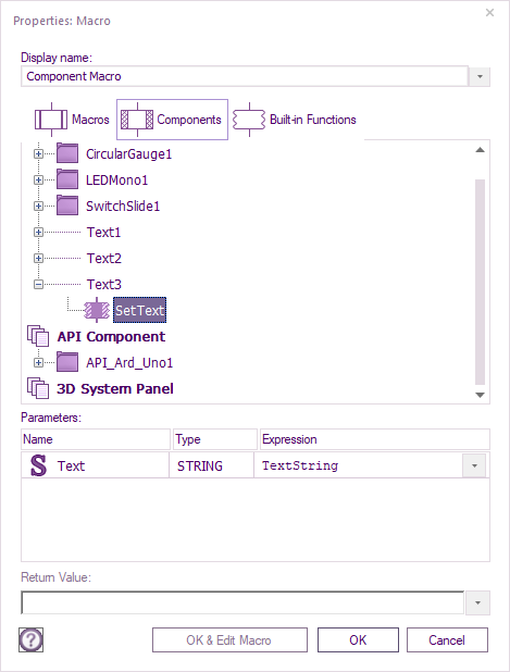
Expand the Text3 by left-clicking on the + symbol, then drag SetText to just below the calculation icon.
Its properties macro will automatically open.
Left-click on the dropdown,just below Expression and Double left-click on the TextString variable and slect OK
LDouble left-click on the Text3 component, left-click on the down arrow for the expression input box, and place double left-click the string variable you just added:
Select OK, then Save the project.
What we have just done, converts the integer variable into a string so it can be displayed on the 2D text.
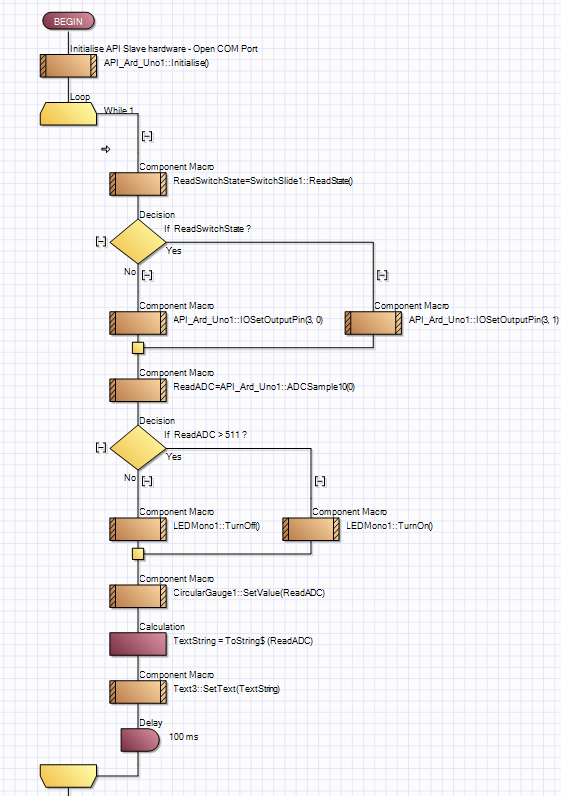
The finished flowchart should look like this:
Rather than single-stepping, you can run a simulation and still be able to view the variables.
Within the Debug ribbon, left-click Go.
When the Simulation debugger pops up, move the slider, so you see Simulation speed: Fast (with updates)
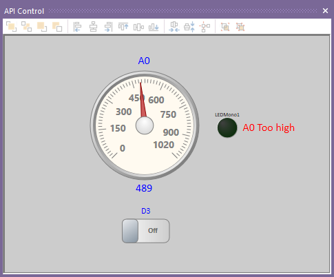
If all is working, with the potentiometer set for about 2.1V across A0 and ground
The ReadADC variable on my flowchart is at 489:
Note the indicator is off.
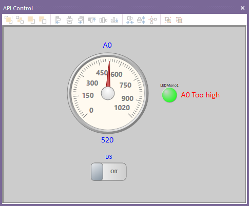
Rotate pot slightly, so A0 rises to over 511:
You are now running your first PC Developer project.
PWM, Servos, OneWire etc can be added and there will not be any requirement to update the firmware on the Arduino.
