Difference between revisions of "DSP"
| Line 51: | Line 51: | ||
[[File:DSP2.jpg]] | [[File:DSP2.jpg]] | ||
| + | |||
| + | |||
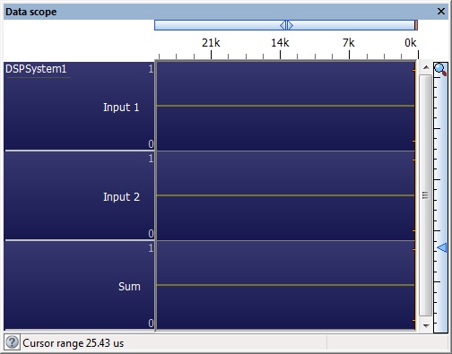
| + | The DSP system initialise function must be called in your program before any other DSP component macros are called as it sets up the buffers ready to be used. The initialise function also sets up the scope window so if you like you can see the DSP signals during simulation to help debug or visualise what's going on. | ||
| + | |||
| + | [[File:DSP5.jpg]] | ||
Revision as of 16:43, 5 March 2014
What is DSP
DSP or Digital Signal Processing is a way of processing data in way that provides some kind of additional functionality. DSP usually takes the form of an input, a process on the input and an output corresponding to the process. As microcontrollers are generally quite fast devices it is the act of repeating the process at high speed that allows us to perform the task in hand.
These are all potential examples of a DSP system at work:
Guitar Distortion
Audio effects e.g. Echo, Reverb, etc.
Digital Filtering
Frequency Spectrum Analysis
Baby Monitors
Covert Listening Devices (Bugs)
Speed Control
Position Control
Temperature Control
The DSP System Component
There are a number of components built into Flowcode to help you to create a DSP system specific for what you need.
The DSP components all centre around the DSP System component which is basically the buffer manager for the system. For each link between components we need a buffer, think of each buffer as a pipe that the data can flow along. The size of each buffer dictates the number of operations or "ticks" that have to happen before the data reaches the end of the buffer. If we know the "tick" rate of the system and the size of the buffer then we know the delay that will be presented when the data is travelling through the buffer.
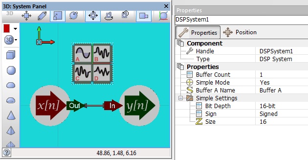
For example if we have an input component connected directly to an output component then we need only one buffer.
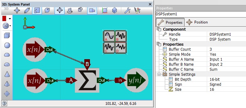
If we have two input components connected via a sum component and then onto an output component then we need three buffers. Naming the buffers can help when it comes to connecting everything up.
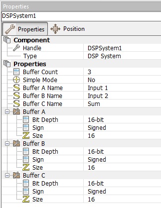
By default all the buffers have the same bit depth and sign but by disabling the simple mode property these can be manually edited for each individual buffer.
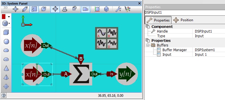
Components are connected up to the buffers by specifying the buffer manager and then selecting the buffer.
The DSP system initialise function must be called in your program before any other DSP component macros are called as it sets up the buffers ready to be used. The initialise function also sets up the scope window so if you like you can see the DSP signals during simulation to help debug or visualise what's going on.
