Difference between revisions of "Using the Data Recorder"
| Line 5: | Line 5: | ||
| − | === | + | ===Introduction=== |
| − | + | Flowcode includes a data recorder ideal for testing your applications in both hardware and simulation. | |
| + | It works alongside Ghost Technology to allow users to monitor signals in real time using In-Circuit-Test. It can also be used in simulation mode, though timing of signals is not accurate when using simulation. In simulation, it allows the user to see the results and values from raw data and components such as dials and measures. This data allows you to monitor the state of the various signals plotted to various channels. | ||
| − | + | <!--Image of Data Recorder--> | |
| + | The data recorder is very useful for analyzing data as it can accurately display information to identify patterns in the data as well as the speed data is being displayed at. Components such as the DSP range will automatically create their own Data Recorder channels, allowing for very simple yet powerful means of monitoring and debugging the system. | ||
| − | |||
| + | ===How to use=== | ||
| − | + | ====Adding streams==== | |
| + | Streams are separated via two types: user streams and program streams. | ||
| − | + | =====User streams===== | |
| + | User streams are simple streams that allow you to easily monitor the value of a digital or analog pin. They can be added by simply clicking the “Add pin trace” button on the data recorder itself and selecting the appropriate digital or analog pin. | ||
| − | + | This method of adding streams is recommended if you are using Ghost technology (link) to view live pin data from your Matrix hardware. | |
| − | + | <!--Image here of Add pin trace button.--> | |
| − | + | =====Program streams===== | |
| − | + | Program streams are added by components or by flowchart icons in your program. For some components, simply adding it to the 2d or 3d panel causes a program stream to appear in the data recorder. These streams are then controlled by the component itself and will be removed automatically when appropriate. | |
| − | + | <!-- Image of program streams added by SPI master.--> | |
| − | |||
| + | Here, we will give an example of creating your own program stream using flowchart icons. | ||
| − | === | + | ======Creating a stream group====== |
| − | + | To create a new stream group you first need to create a global “Handle” type variable to store the reference to the stream group. This is basically a unique number which used to refer to that specific group of streams in the data recorder. To do this, open the [[Project_Explorer|Project Explorer]] window and select the “Globals” tab. Next, right click the “Variables” portion of the tree view and select “Add New” from the menu. In the “Create a New Variable” dialogue that pops up give the variable a meaningful name such as “DRGroupHandle”, then switch the variable type to “Object handle” and click “OK”. You should then get an Object handle variable appearing in the [[Project_Explorer|Project Explorer]] window. | |
| − | |||
| + | [[File:Scope1.jpg]] <!--Created handle variable called DRGroupHandle--> | ||
| − | |||
| + | Next, we need to assign the handle variable with a value by calling the Flowcode API. To do this we add a Simulation Macro (link) icon to the “Main” flowchart. Then we double-click the icon on the flowchart to edit the icon's properties. Inside the icon property window we first need to ensure that the “Functions” tab is selected and then scroll down to the “DataRecorder” section before clicking the + icon to see all the API calls related to the data recorder’s functionality. | ||
| − | |||
| + | [[File:Scope2.jpg]] <!-- List of DataRecorder API functions --> | ||
| − | |||
| + | The [[API_Scope.AddGroup|AddGroup]] function call creates a new named group of streams on the data recorder. The return value of the function call requires a handle type variable. You should set this to the name of the variable we have created previously (“DRGroupHandle” in this example). Type a name that you want into the parameter field, (such as “Test Group”). | ||
| − | |||
| + | [[File:Scope3A.jpg]] <!-- Image of AddGroup with variable entered and “Test Group” --> | ||
| − | |||
| + | The [[API_Scope.AddStream|AddStream]] function call adds a new named stream to the group on the data recorder. The return value of the function call is a handle type variable. We will have to create a new global object handle type variable to store this. This handle must be unique for each single stream so you must use a new object handle variable for every program stream that you create on the data recorder. | ||
| − | + | [[File:Scope3B.jpg]] <!-- Image of AddStream with DRGroupHandle, DRStreamHandle return --> | |
| + | When we run the simulation the new group will be created on the data recorder ready for data to be streamed in. | ||
| − | |||
| + | [[File:Scope3.jpg]] <!-- flow icons and created stream image --> | ||
| − | |||
| + | If you are creating your own Flowcode component, you can move these from the Main macro to the [[Event_Components.Initialise|simulation initialise event]] macro so that the group and stream are created automatically when the component is added to a program. This is the way that components such as the DSP based components add their data to the console window. | ||
| − | |||
| + | [[File:Scope4.jpg]] <!-- Ev_initialise image --> | ||
| − | + | Note that a group with no valid stream handles will not show up on the data recorder window just to try and avoid potential unnecessary clutter. | |
| + | Setting the handle variable to the value of 0 using a [[Calculation_Icon_Properties|Calculation icon]] or calling the [[API_System.DeleteHandle|System -> DeleteHandle]] API call will remove the group or stream from the data recorder window. | ||
| − | + | ======Adding a digital pin or port to a program stream====== | |
| − | |||
| − | |||
| − | |||
| − | |||
| − | |||
| − | |||
| − | |||
| − | |||
| − | |||
| − | |||
| − | |||
| − | |||
| − | |||
| − | ===Adding a digital pin or port to a stream=== | ||
Revision as of 09:40, 16 May 2019
<sidebar>Sidebar: Flowcode Help Overview:ToolsViews</sidebar>
Contents
Introduction
Flowcode includes a data recorder ideal for testing your applications in both hardware and simulation.
It works alongside Ghost Technology to allow users to monitor signals in real time using In-Circuit-Test. It can also be used in simulation mode, though timing of signals is not accurate when using simulation. In simulation, it allows the user to see the results and values from raw data and components such as dials and measures. This data allows you to monitor the state of the various signals plotted to various channels.
The data recorder is very useful for analyzing data as it can accurately display information to identify patterns in the data as well as the speed data is being displayed at. Components such as the DSP range will automatically create their own Data Recorder channels, allowing for very simple yet powerful means of monitoring and debugging the system.
How to use
Adding streams
Streams are separated via two types: user streams and program streams.
User streams
User streams are simple streams that allow you to easily monitor the value of a digital or analog pin. They can be added by simply clicking the “Add pin trace” button on the data recorder itself and selecting the appropriate digital or analog pin.
This method of adding streams is recommended if you are using Ghost technology (link) to view live pin data from your Matrix hardware.
Program streams
Program streams are added by components or by flowchart icons in your program. For some components, simply adding it to the 2d or 3d panel causes a program stream to appear in the data recorder. These streams are then controlled by the component itself and will be removed automatically when appropriate.
Here, we will give an example of creating your own program stream using flowchart icons.
Creating a stream group
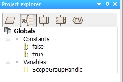
To create a new stream group you first need to create a global “Handle” type variable to store the reference to the stream group. This is basically a unique number which used to refer to that specific group of streams in the data recorder. To do this, open the Project Explorer window and select the “Globals” tab. Next, right click the “Variables” portion of the tree view and select “Add New” from the menu. In the “Create a New Variable” dialogue that pops up give the variable a meaningful name such as “DRGroupHandle”, then switch the variable type to “Object handle” and click “OK”. You should then get an Object handle variable appearing in the Project Explorer window.
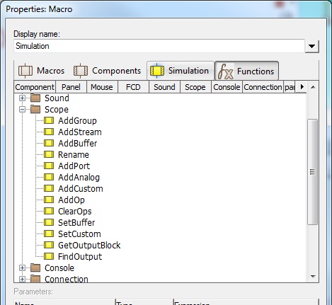
Next, we need to assign the handle variable with a value by calling the Flowcode API. To do this we add a Simulation Macro (link) icon to the “Main” flowchart. Then we double-click the icon on the flowchart to edit the icon's properties. Inside the icon property window we first need to ensure that the “Functions” tab is selected and then scroll down to the “DataRecorder” section before clicking the + icon to see all the API calls related to the data recorder’s functionality.
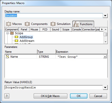
The AddGroup function call creates a new named group of streams on the data recorder. The return value of the function call requires a handle type variable. You should set this to the name of the variable we have created previously (“DRGroupHandle” in this example). Type a name that you want into the parameter field, (such as “Test Group”).
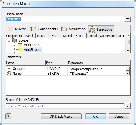
The AddStream function call adds a new named stream to the group on the data recorder. The return value of the function call is a handle type variable. We will have to create a new global object handle type variable to store this. This handle must be unique for each single stream so you must use a new object handle variable for every program stream that you create on the data recorder.
When we run the simulation the new group will be created on the data recorder ready for data to be streamed in.
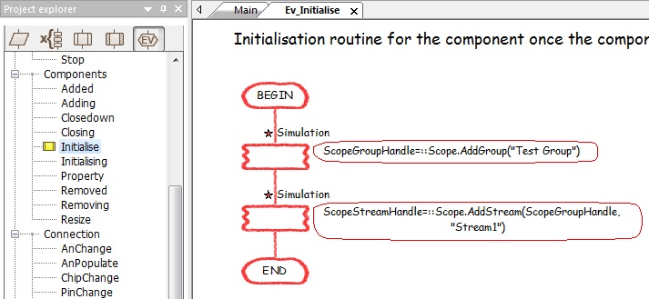
If you are creating your own Flowcode component, you can move these from the Main macro to the simulation initialise event macro so that the group and stream are created automatically when the component is added to a program. This is the way that components such as the DSP based components add their data to the console window.
Note that a group with no valid stream handles will not show up on the data recorder window just to try and avoid potential unnecessary clutter. Setting the handle variable to the value of 0 using a Calculation icon or calling the System -> DeleteHandle API call will remove the group or stream from the data recorder window.
Adding a digital pin or port to a program stream
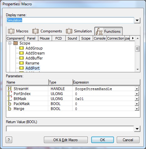
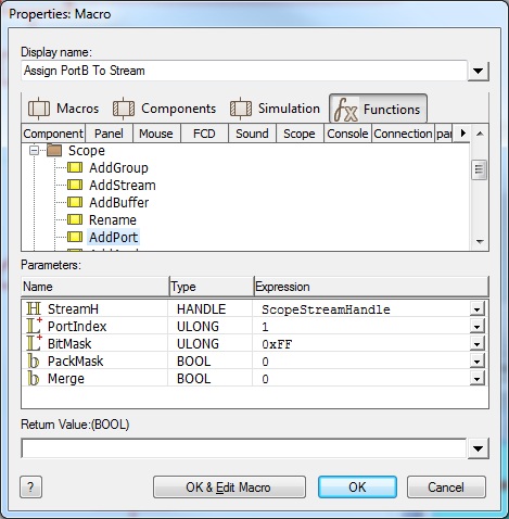
A digital pin or port can be assigned to a stream object handle by using the AddPort function call. The function requires the stream object handle, the port index where PORTA is 0, PORTB is 1 etc. The BitMask parameter is a binary AND mask which selects which bits of the port will be available on the scope stream. The PackMask parameter will move all the active bits together if necessary. The merge parameter allows you to add multiple ports or pins to a single stream.
To monitor a single pin with a LED connected to port pin A0 we can simply call the AddPort function like this.
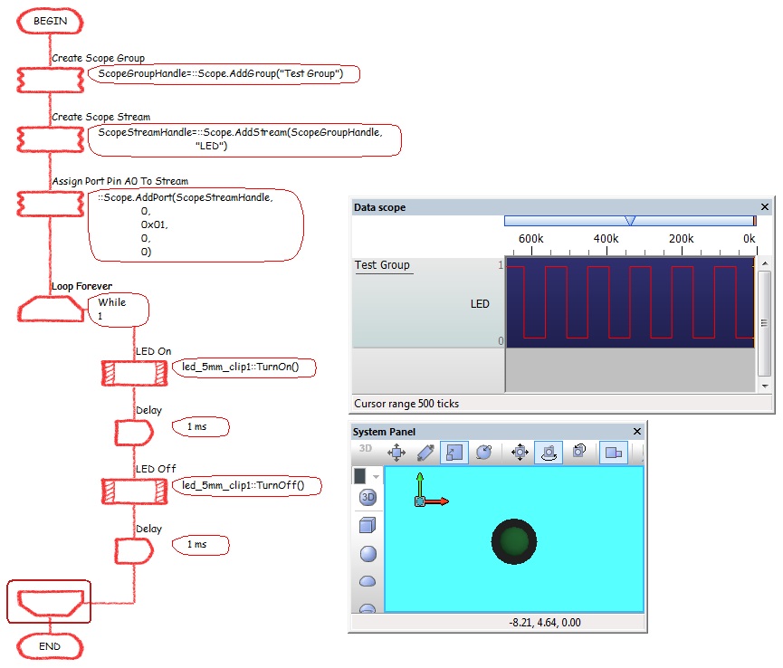
Here is a simple program to toggle the LED with the signal being replicated on the scope trace.
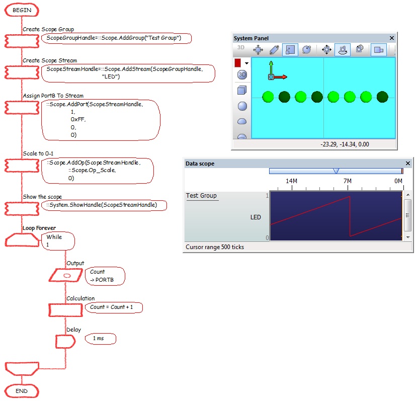
To monitor a full port with a LED Array connected to PortB we can simply call the AddPort function like this.
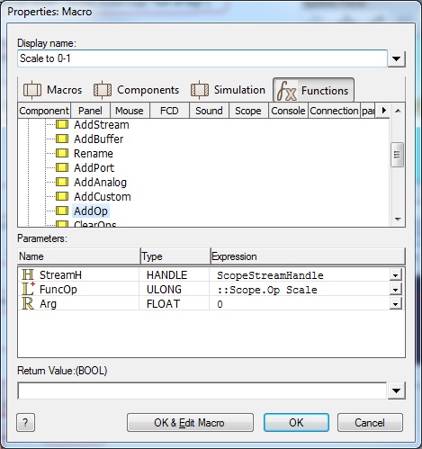
We then need to scale the scope channel to get the value in the range of 0-1 by calling the AddOp function like this.
Here is a simple program to generate a digital counter on the port with the signal being replicated on the scope trace. The ShowHandle function allows the Scope window to appear automatically without the user having to manually open the Scope window.
Adding an analogue pin to a stream
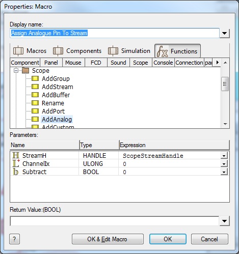
An analogue pin can be assigned to a stream object handle by using the AddAnalog function call. The function requires the stream object handle, the analogue channel index where AN0 is 0, AN1 is 1 etc. The subtract parameter allows you to add or subtract multiple analogue signals on a single stream.
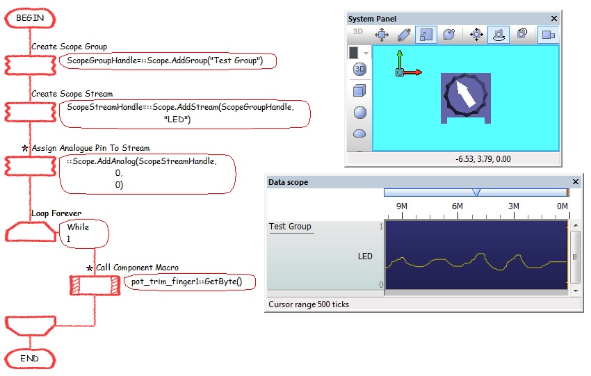
To monitor a single analogue pin with a potentiometer connected to pin AN0 we can simply call the AddAnalog function like this.
Here is a simple program to track the value of an analogue input signal based on the position of the potentiometer.
Adding an custom value to a stream
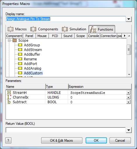
A custom value can be assigned to a stream object handle by using the AddCustom function call. The function requires the stream object handle, the custom channel index 0-31 for each stream handle. The subtract parameter allows you to add or subtract multiple signals on a single stream.
To create a single custom stream we can simply call the AddCustom function like this.
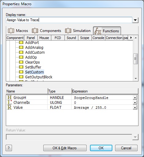
The data for a custom channel cannot come from a digital or analogue channel automatically so instead we have to manually pass the data to the custom channel. This is done by using the SetCustom function call. The value passed should be a floating point real number in the range between 0 and 1 so to convert a byte variable we have to divide by the value 255.0.
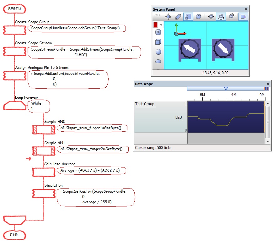
Here is a simple program to track the values of two analogue input signals and then calculate and plot the average between the two readings.
