Difference between revisions of "Digital Pins"
(Created page with "right|332x290px The '''Analog Window''' displays and monitors analog values on each channel, allowing you to see the results/values of each c...") |
|||
| (6 intermediate revisions by 2 users not shown) | |||
| Line 1: | Line 1: | ||
| − | + | The '''Digital Pins''' displays and monitors digital pin values on each digital port pin, allowing you to see the results/values of each port both as a logic 0 or 1. | |
| − | The ''' | ||
| + | To open the 'Digital Pins Window' select 'Digital Pins' from the 'View' menu. | ||
| − | + | The Digital Pins Window dynamically displays the component name and the values of digital pins and can display the data from all of the digital port pins on the device. | |
| − | + | [[File:DigitalPins.jpg]] | |
| − | + | A pin which is pulled to VCC is shown in red with the value 1. | |
| − | |||
| − | |||
| − | |||
| − | |||
| − | + | A pin which is pulled to GND is shown in grey with the value 0. | |
| − | + | ||
| − | + | This corresponds with the pins shown on the [[Chip_View|target device window]] and [[Using_the_Project_Explorer#Ports|Ports of the Project explorer]]. | |
| − | + | ||
| − | + | ||
| − | + | While the simulation is running the state of a pin can be toggled by clicking on the icon in the right hand side field. | |
Latest revision as of 08:20, 21 March 2023
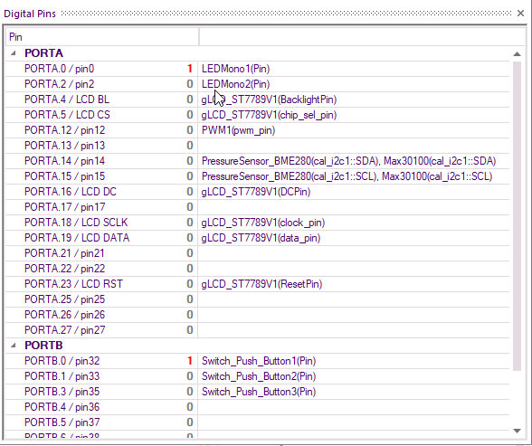
The Digital Pins displays and monitors digital pin values on each digital port pin, allowing you to see the results/values of each port both as a logic 0 or 1.
To open the 'Digital Pins Window' select 'Digital Pins' from the 'View' menu.
The Digital Pins Window dynamically displays the component name and the values of digital pins and can display the data from all of the digital port pins on the device.
A pin which is pulled to VCC is shown in red with the value 1.
A pin which is pulled to GND is shown in grey with the value 0.
This corresponds with the pins shown on the target device window and Ports of the Project explorer.
While the simulation is running the state of a pin can be toggled by clicking on the icon in the right hand side field.
