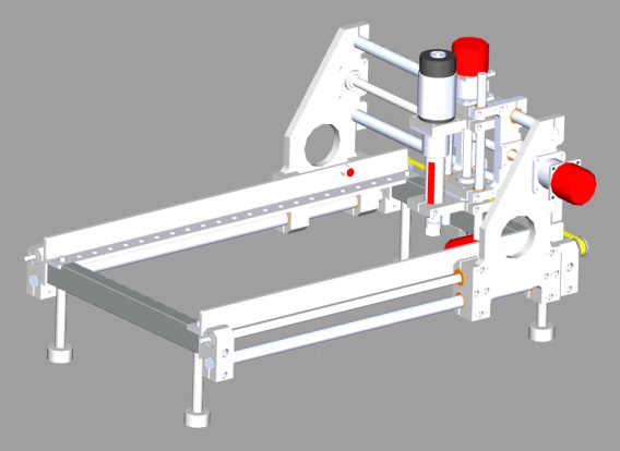
CNC Machine
CNC machines are automated tools, used for a variety of tasks, but primarily in the processing and shaping of materials.
In this scenario you will begin to program a CNC machine, first using high-level functions, and eventually developing your own low-level functions to directly parse (process) individual G-Codes, the language often used to control CNC machines, and move the machine accordingly.
Contents
Exercise 1
In this exercise students will learn the basic control of the CNC machine.
Implement the initialise, home and XYZ component macros to create a simple routine.
Tasks
- Start a new flowchart and select ‘No chip’ as the target device.
- Add the CNC Machine component to the System Panel, found in the 'Simulation -> Scenarios' category.
- You will need to implement the following macros;
- Initialise, to enable the motors
- Home, to move the CNC machine head to coordinates (0,0,0) - every program you write should home the machine to ensure you always know the position of the head before you get started
- MoveToXYZ, to move the machine head to the desired X, Y and Z coordinates
- Create a flowchart that first initialises, then moves between two sets of XYZ coordinates alternately
Note
The Z axis will use a negative value to plunge down into the material being cut. Negative values can only be stored in Signed or Float type variables.
Working Example
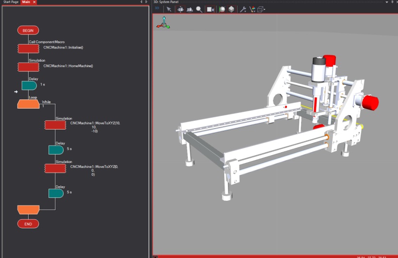
Below is a working example for example 1, which initialises, then homes the machine and finally features a loop which moves the machine head between coordinates (0,0,0) and (10,10,-10).
What to do next
Modify the program to create a routine of 10+ sets of coordinates. Consider the use of an array to store the sets of coordinates.
Exercise 2
In exercise 2 you will re-create the Home component macro, using some of the lower level functions. You will need to implement macros such as AxisMovement and ResetCoords.
Tasks
- Open the flowchart from Ex1 and continue working from there.
- Create a variable to determine when each of the axes has reached the limit switches (the AxisMovement macros will return a ‘1’ if a collision is detected, otherwise a ‘0’).
- First, initialise the CNC machine
- Create a loop which moves the X-axis by 1 step, using the XMovement macro. Each time it is moved, read the return value to determine if it has reached the limit switch.
- Repeat the above steps for both the Y and Z axis
- Once all 3 axes are homed, call the ResetCoords macro to set all the zero values into memory of the CNC machine.
What to do next
Look at the program you just made. Can you simplify it further using only one variable to determine when the limit switches are pressed, instead of three? Efficient coding is a valuable skill for any engineer.
Exercise 3
As with exercise 2, students will create their own high-level macros from low-level ones. Here, students should work to re-create the macro ‘MoveToXYZ’ using the AxisMovement macros. Note, limit this to 2D first, then progress to 3D. Students will be required to consider the linear interpolation, and how to move from its current position, to the new desired position.
Tasks
- Open the flowchart from Ex2 and continue working from there.
- Consider any variables you may need, and ensure they are created.
- Ensure you Initialise and Home the machine.
- Create a macro and call it ‘GoToXY’, and set it up to receive two parameters; X and Y.
- Within this macro, first determine the current position of the machine head - you should create two global variables to track this
- Once the current position is known, determine where the new position is, and work out the difference (this could be a positive OR negative value).
- Next, work out the ratio of movement for the X and Y axis. For example, assume you are at position (0,0), and want to go to (5,10). The Y axis must move twice as far as the X axis. Therefore, for every step of the X-axis, you must move 2 of the Y-axis.
- Once you have reached the new position, update the global variables for the current position and exit the macro.
What to do next
Once you have achieved 2D linear interpolation, you should consider adding the third Z axis.
Exercise 4
Typically, CNC machines operate from G codes, a set of commands that automate where the machine has to go to, and at what speed to drill/ mill etc. When creating a Computer Aided Manufacture (CAM) file for a CNC machine, there are tools for creating G Code.
In this exercise, students will work towards creating a macro to parse (read and interpret) a line of G Code to the MoveToXYZ macro. Students will have to consider how to receive a string of text from a typical line of G code, and extract the relevant information for the MoveToXYZ macro.
Tasks
- Continue from Ex3
- Create two string type variables, and set their default values to;
- “G00 X0 Y0 Z0”
- “G00 X5 Y10 Z-10”
- Create a macro called ‘GCodeParser”. Parsing is to break down a string of text and extract the relevant parts, here the X,Y and Z information.
- Create a parameter in the create macro dialogue box of type string. This is used to send either of the G Code command strings to the macro.
- Create 3 local variables within the new macro to save the X, Y and Z values.
Note
There are many G Codes, G00 is the most basic. A true G code parser would be able to differentiate and action a wide array of G code commands.
What to do next
Modify your GCodeParser to be able to differentiate between two G Code commands; G00 - Rapid Positioning, and G01 - Linear Interpolation. Do not worry about the specifics, mainly just the ability to process the data differently for different command types.
Component Details
A full listing of the macros and properties available in this component are available from the Components Section.

