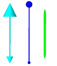
API Panel.LinkBar.Create
| Create | |
| Creates a new bar linking a pair of position handles | |
| StartPos | |
| The start position to set the link to | |
| EndPos | |
| The end position to set the link to | |
| Return | |
Detailed description
This creates a graphical link between two positions. The positions StartPos and EndPos may be any component or position handle, or textual component name.
Links are created as visible and auto-tracking. A link can be set as fixed (at start or end) using the SetStartPos and SetEndPos calls.
By default, links will 'clip' with the edges of the positions they connect - that is, the end of the link is drawn at the intersection with the position objects bounding box. This behavior can be modified using SetStartAdjustment and SetEndAdjustment.
Link bars are not only useful for representing a physical link between two objects, but if hidden can be used in kinematics for calculating the distances and angles between the objects. Regardless of the offsets and clipping adjustments, the ray the bar is drawn along will always pass through the center points of the start and end positions.
When the link is first created, it has default attributes - a default colour and mode, which is a simple line with no start or end caps. The calls of this API to set the graphic modes can alter this and build the links up as required to set colour and cap types.
Note that link bars are not considered physical obejcts in the truest sense by Flowcode. That is, they do not cast shadows and are not considered when exporting meshes or in collision detection.
Examples
Calling in a calculation
- Declare a variable 'result' of type HANDLE
- Add to a calculation icon:
result = ::Panel.LinkBar.Create(startpos, endpos)
