Configuring the Chip
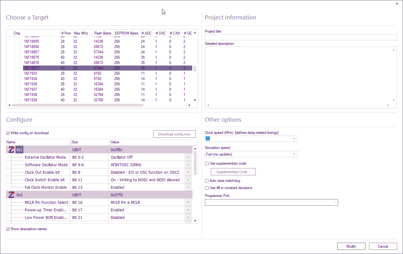
The chip can be configured from the 'Configure' section within Project Options accessed from the 'Build' ribbon (Build > Project Options).
Please note that it is important to check the configuration before downloading to a chip.
Please ensure that the chip type and oscillator type are correct for your program as these are the main source of user problems.
Some of the more popular devices will have a default configuration which assumes a few of the more popular settings.
As a rule of thumb, any feature you are not specifically using should be disabled.
Leaving any of the following enabled will likely cause issues for your application: low voltage programming, watchdog timer, extended CPU.
Configuring the chip for PICmicros
Clicking on the Configure tab from within the Project Options calls up the Configuration page, which allows you to customize settings for your current chip.
The configuration page can be used to:
Set the oscillator type required
Enable/disable advanced features such as brown out, watchdog timers, low voltage programming, read protection etc.
If you are using Flowcode for the very first time, or have changed development boards, you may need to check the options to set which board you are using.
Video instructions
For further details watch the Configuring the Chip video for instructions describing how to configure the chip using the 'Configure' tab in the 'Project Options' which is accessed from the 'Build' menu (Build > Project Options > Configure).
Manually configuring the chip for PICmicros
See Selecting Compiler Options (PICmicro) for help with switching off the default configuration options that use PPP.
Once you have disabled the default configuration options you can enter your own configuration data. For the PICmicro this data will be sent to the chip every time you perform a compile to chip operation.
An example configuration word for the PIC16 series is
0x2007, 0x3FFC
The 0x2007 is the location in memory of the configuration word and the 0x3FFC is the configuration word itself.
An example set of configuration words for the PIC18 series is
0x300000, 0x00
0x300001, 0x22
0x300002, 0x0D
0x300003, 0x0E
0x300004, 0x00
0x300005, 0x00
0x300006, 0x80
0x300007, 0x00
0x300008, 0x0F
0x300009, 0xC0
0x30000A, 0x0F
0x30000B, 0xE0
0x30000C, 0x0F
0x30000D, 0x40
Configuring the Chip for AVRs
The chip can be configured from the Configure option in the chip menu.
Please note that it is important to check the configuration before downloading to a chip.
Configuration settings for individual devices may be represented by 1, 2 or 3 bytes
The function of many of the individual configuration bits are also device dependent.
The data sheet for the relevant target device should be consulted before sending configuration data.
The default setting is configured to send the hex value 0xdf (223 decimal) to parameter location 0
The parameter locations are:
0 = Fuse High Byte (hfuse)
1 = Fuse Low byte (lfuse)
2 = Extended fuse Byte (efuse)
An example of 3 bytes of configuration data is shown below
OK and Send
Save the configuration data and send to the target device
OK
Confirm the configuration data but do not send to the target device
Note: Configuration memory might have a lower endurance than program memory. Only send configuration data when changes are required.
AVR's can also become locked if incorrect configuration settings are loaded so take care when transferring the settings to a device.
