Ghost Technology
Contents
What is Ghost Technology?
Ghost is a technology which, when combined with Flowcode, provides a revolutionary way of debugging electronic systems.
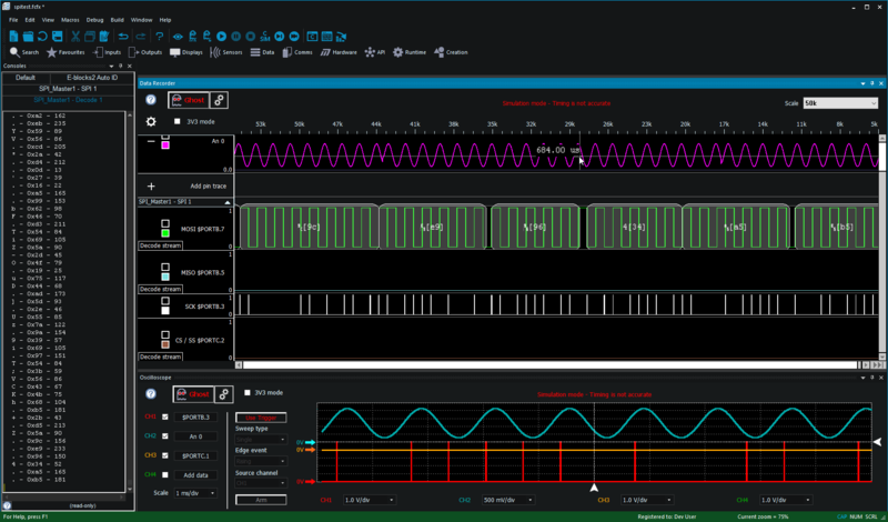
Ghost technology provides a real time log of the status of all the pins on the microcontroller while a program is running on the device. The data is viewed on the Flowcode Oscillscope or Data Recorder. We call this ‘In-Circuit-Test’.
It also provides the ability to control the program that is running on the microcontroller from Flowcode itself. You can run, pause, and step through your program and view Ghost data at the same time. View variables, registers and other memory locations. We call this “In-Circuit-Debug”.
When Ghost is combined with the PC-side processing capabilities of Flowcode it provides a very powerful debugging and learning tool. This saves huge amounts of development time - whether you are working at a pin level and getting your first program to work, or whether you are an advanced user wanting to perform a sanity check to make sure communications baud rates are set at the correct speed.
Both analogue and digital data is gathered through Ghost and displayed on the Flowcode Oscilloscope and Data Recorder. For communications busses, decoding overlays for SPI, I2C, and other comms standards are available. Ghost data can also be passed to simulation/SCADA components in Flowcode to provide Human Machine Interface style debug features. You can find an example here.
Ghost is watching over your hardware!
In-Circuit-Test (Pin monitoring)
In-Circuit-Test (ICT) functionality is a key feature provided by Ghost. It allows monitoring of all the external signals of your target microcontroller by displaying real time signal data on the Oscilloscope or Data Recorder. Signal data corresponding with communication busses can be decoded with the data appearing in a nice formatted way on either the Data Recorder or the Console Window. When ICT is enabled or disabled there is no need to re-program the target device. It is not possible to use ICT when Flowcode simulation is running, unless you are running ICD mode (see the section on ICD below).
Supported hardware
- Matrix EB006 PIC Multiprogrammer Version 9
- Matrix EB091 dsPIC Programmer
- Matrix Flowkit II ICD tool - Compatible with Arduino and 3rd party hardware.
- Matrix BL0011 PIC Programmer
- Matrix BL0032 dsPIC Programmer
- Matrix BL0036 Raspberry Pi shield
- Matrix BL0061 ARM Programmer
- Matrix BL0080 PIC Multiprogrammer
- Matrix BL0055 Arduino Shield
- Matrix BL0086 AVR Programmer
How to use
- Plug your board into your PC and ensure that the correct drivers are installed (found in the Flowcode install directory)
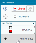
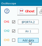
- Add your chosen pins to the Data Recorder or Oscilloscope
- Click the Ghost button on the Data Recorder or Oscilloscope
Please click here to learn more about the Data Recorder
Please click here to learn more about the Oscilloscope
In-Circuit-Debug (Remote control of execution)
In-Circuit-Debug (ICD) allows breakpoints, single stepping, and other simulation features such as the Simulation Debugger to work seamlessly with your program running directly on the target Microcontroller.
When ICD is enabled you must re-program the target device to allow the ghost specific code to be loaded onto the target device. Once the device has been programmed, it will stay in a waiting state until Flowcode signals it to start running. Clicking the simulation run or step buttons in Flowcode will trigger the target device to react accordingly. Clicking the simulation stop button will reset the target device so that it restarts from the very start of the program. When disabling ICD you again need to re-compile and program the device to allow the ghost specific code to be removed from the program.
Supported hardware
- Matrix EB006 PIC Multiprogrammer Version 9
- Matrix EB064 dsPIC Multiprogrammer Version 2
- Matrix EB091 dsPIC Programmer
- Matrix Flowkit ICD tool - Compatible with MIAC, ECIO, FormulaFlowcode and 3rd party hardware.
- Matrix Flowkit II ICD tool - Compatible with Arduino and 3rd party hardware.
- Matrix BL0011 PIC Programmer
- Matrix BL0032 dsPIC Programmer
- Matrix BL0036 Raspberry Pi shield
- Matrix BL0061 ARM Programmer
- Matrix BL0080 PIC Multiprogrammer
- Matrix BL0055 Arduino Shield
- Matrix BL0086 AVR Programmer
How to use
- Develop your program using Flowcode as normal until you are ready to test the results.
- With a Ghost-compatible board connected, click on the Enable ICD button which is located within the Debug ribbon so that the Execute icons (Run, Pause, Stop etc. ) changes to green and a blue border will appear around the Enable ICD icon
- Only if you want to use ICD, Click Build ribbon Compile To Target..., to send the Ghost code to your device.
- Within the Debug ribbon, Click Play button or Step Into / Step Over to begin execution.
- When you are finished. Click Stop and then the Enable ICD button again, so that the toolbar returns to its original colour. Click Compile-To-Chip again so that the Ghost code is removed from the program.
Note that you can slow down execution speed using the Simulation Debugger window and monitor the values of variables in the same way as when you are using simulation. ICT is also available when running your program via ICD.
Advanced Ghost Settings
For advanced users, you can modify certain operating parameters for Ghost in its settings window. If you have a Ghost device plugged into your PC, you can click the double cog icon on the Oscilloscope or Data Recorder, or the Ghost settings icon on the main toolbar to open the Ghost settings.
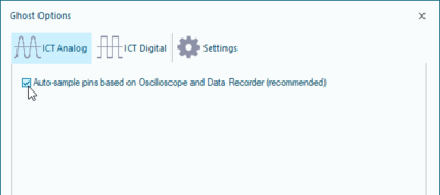
Sample masks
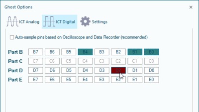
You can set the sample mask that Ghost uses to decide which pins should be recorded. It is recommended for most cases that you leave this set to automatic mode.
However, if you wish to set the sample mask manually, you can uncheck the box and choose which pins should be sampled.
General settings
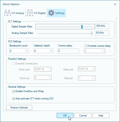
The settings tab controls various aspects of the ICD and ICT functionality.
ICT Settings: Controls the digital and analog sample rates, note that the analogue sample rate is scaled based on the digital sample rate.
ICD Settings: Controls the number of breakpoints, the maximum size of the stack and the communications time-out delay.
Flowkit 2 Settings: Only configurable when you have a FlowKit 2 board connected, these control the two target pins used for ICD communications. These pins cannot be used in your program or you risk ICD communications being unreliable or unavailable.
Enable Overflow and Wrap: This controls what happens if the ICT buffer runs out of memory.
- Checked: If the ICT buffer runs out of memory then the contents of memory are wiped allowing ICT to continue, you may notice a glitch on your scope traces.
- Unchecked: If the ICT buffer runs out of memory then ICT mode is automatically switched off, this guarantees that there are no glitches in the data.
Auto-activate ICT when running ICD: This automatically toggles ICT (pin sampling) when ICD is running. Note that there is no other way to make use of the data recorder otherwise, as simulation data is not available in ICD mode.
