Project Options
<sidebar>Sidebar: What Is a Flowcode Flowchart?</sidebar> This window defines settings related to the current Flowcode project. The window can be viewed by selecting 'Project Options' in the 'Build' menu (Build > Project Options...).
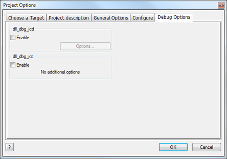
These options allow you to customize your project and alter the fundamental functions of the project by changing the target chip, clock speed and simulation speed and even configure the chip itself by editing the configuration settings, you can also enable and configure the 'Debug Options' which allow the user to run in ICD mode and use ICT and analog monitoring as well as overriding the ICD pins.
Choose a Target
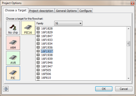
Choose a target for this flowchart
This tab allows you to select a target chip from all the currently supported devices by Flowcode. Users can select a new chip or change the chip from this menu.
Devices are shown via chip types and then by device types to allow you to easily find what device and chip you wish to target.
You can also choose 'No chip' to create a simulation-only chip which will allow you to use a massive range of ports to connect to although you cannot download your flowchart program to a device, you can expand your options for simulation-only projects.
Project Description
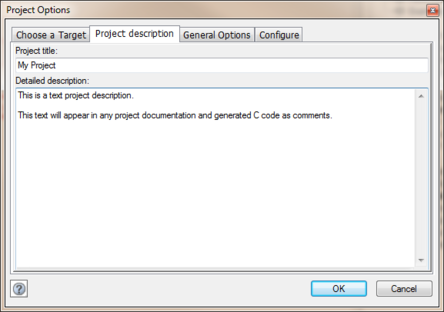
Project title
Here users can give their project a title, this title will appear in the generated C code and in any of the documentation features of Flowcode.
Project description
Allows users to give a detailed description of the project. This information will appear in the generated C code and in any of the documentation features of Flowcode.
General Options
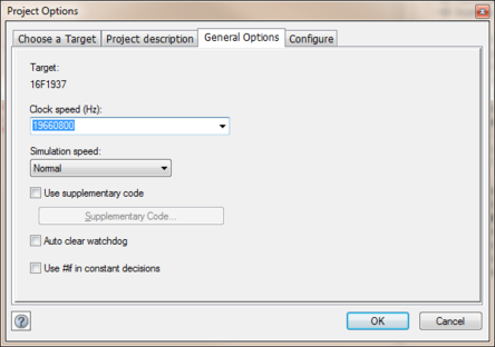
Target
Defines the microcontroller that the Flowcode compiled program will be run on.
Configuring the Chip
Allows the user to configure the target chip.
Clock Speed
Must be set to match the hardware clock frequency so that delays and other timing critical features run at the correct speed on the hardware. Several options exist for the clock speed in the drop down menu however any value of clock speed can be entered directly into the text field.
Simulation Speed
Defines the speed of the flowchart simulation. Slowing down the simulation allows for flowchart icons to become highlighted as the simulation runs.
Use Supplementary Code
Allows any supplementary code to be included into the program. This is useful for including external C or Assembler files into your programs.
Auto Clear Watchdog
This is used to automatically clear the watchdog timer every time a component macro is called which will stop the target device from detecting a false stop condition and resetting.
Use #if in Constant Decisions
Uses the preprocessor to optimise the code in if / else blocks if a constant is used in the condition statement.
Configure
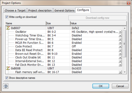
In this tab you can configure the chip in many ways, from simply setting the oscillator type to enabling and disabling advanced features such as brown out, watchdog timers, low voltage programming, read protection etc.
Manually configuring the chip for PICmicros
See Selecting Compiler Options (PICmicro) for help with switching off the default configuration options that use PPP.
Once you have disabled the default configuration options you can enter your own configuration data. For the PICmicro this data will be sent to the chip every time you perform a compile to chip operation.
An example configuration word for the PIC16 series is
0x2007, 0x3FFC
The 0x2007 is the location in memory of the configuration word and the 0x3FFC is the configuration word itself.
Debug Options
The 'Debug Options' allow you to enable ICD mode and configure ICD options as well as enable and configure ICT and Analog monitoring. You can also override the ICD pins and specifically change the port and pin connections.
ICD or In Circuit Debug can be used to monitor and control the programs execution in the real hardware using Flowcode as the front end. When ICD is enabled and you have programmed the current version of the Flowcode program to the microcontroller device, starting the Flowcode simulation will trigger the hardware to start. Pausing an active simulation will pause the microcontroller and allow you to read and or write variables or registers. Stepping through and breakpoints also work with ICD mode.
ICT or In Circuit Test can be used to monitor all of the pins of the microcontroller device in either digital or analogue modes in near real time. ICT is useful to sanity check that signals are changing correctly on hardware, busses are running correctly at the correct speed and external modules are enabled and returning correct data. The incoming ICT waveforms can be made to appear in the scope window and used to control the Flowcode simulation.
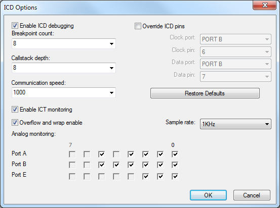
Enable ICD debugging
Switches on the ICD functionality. An appropriate Matrix ICD tool is required, such as FlowKit or an EB006 v7 or later.
Breakpoint Count
Defines the maximum number of breakpoints allowed in your program.
Callstack Depth
Defines the maximum stack size in you program. This will always be 8 unless you have enabled the BoostC software stack.
Communication Speed
Defines the number of iterations to wait before timing out. This value is based on the clock speed of the target device and is automatically updated.
Override ICD Pins
Allows any free I/O pins on the target microcontroller to be used for the ICD functionality. Compatible with the matrix ICD tool.
Restore Defaults
Restores all of the ICD settings back to their default values.
Enable ICT monitoring
Switches on the ICT functionality. An appropriate Matrix ICT tool is required, such as an EB006 v9 or later.
Overflow and wrap enable
Determines if the ICT will carry on if the device runs out of memory. When enabled the contents of memory will be deleted to make room for new data to be recorded, this will likely cause glitches in the input waveform but will allow the test mode to continue to run at higher sample rates.
Sample Rate
Determines the speed that the inputs will be sampled. The digital pins will be sampled at the specific rate set, the analogue pins will be sampled one at a time so a 10KHz sample rate with two analogue channels enabled provides 5KHz sample rate on both analogue channels.
Analog monitoring:
Determines which analogue pins are enabled for monitoring. Analogue sample rate is equal to the sample rate divided by the number of active analogue channels.
