Sysblocks Getting Started Guide

Introduction to Sysblocks

Sysblocks and Flowcode 10 provide a new way of teaching about signal processing for Music technology, DSP, Communications and Software Defined Radio.
Hardware:
The opportunity of developing a product like Sysblocks is facilitated by the advent of advent of low cost high speed, high power microcontrollers - in this case a 32bit PICmicro microcontroller. The Sysblock hardware topology is very simple: Input buffer …..A/D….processor...D/A….output amplifer.
Sysblocks boards also include two E-blocks II boards so that students can use a wide variety of expansion boards from Matrix, Grove, Mikroelektronika and others.
Software:
Flowcode 10 software is a graphical programming solution for microcontrollers and PCs. Flowcode allows those with limited programming experience to develop complex electronic systems using graphical and conventional C code programming.
Curriculum: There are three separate curricula for Sysblocks and Flowcode 10:
- Music with microcontrollers
- Systems, signals, DSP, and FFT
- Communications and Software Defined Radio
The following information will explain to you how Sysblocks and Flowcode 10 can be used to provide fantastic learning opportunities in electronics.
Hardware: PCB overview

1. Fast 32 bit PIC processor                                    16. Input switch SW2

2. PIC18F24K50 control processor that handles                   17. E-blocks II expansion port A
   the USB communications, 32 bit PIC programming,
   LCD display, encoders and input switches                     18. E-blocks II expansion port B

3. SMA connector  Input IN0                                     19. USB socket / power in

4. AC / DC coupling switch SW4                                  20. 2.1mm power jack, 5 - 12V

5. SMA connector  Input IN1                                     21. Screw terminal power connector (input or output)

6. AC / DC coupling switch SW3                                  22. 2 x banks of 8 user programmable  LEDs - for VU meters

7. SMA connector Output OUT0                                    23. Grove sensor expansion socket

8. SMA connector  Output OUT1

9. 3.5mm jack stereo line in

10. 3.5mm jack stereo line out

11. 4 line monochrome LCD display

12. Rotary encoder input ENC0

13. Rotary encoder input ENC1

14. Input switch SW0

15. Input switch SW1
Hardware: block diagram

Sysblocks has four analogue inputs, two analogue outputs and support circuitry.
At the heart of the system is a very powerful 32 bit Micro chip PICmicro microcontroller running at 200MHz. This is capable of standard microcontroller type functions and also is capable of Digital Signal Processing the incoming audio signals. The 32 bit processor has a Coremark of 652 (around 330 Drystone MIPS) which is more than fast enough for the signal processing tasks involved for learning about Music technology, Digital Signal Processing and Modern communications theory.
The 32 bit PICmicro microcontroller is programmed by a host device which is a standard 18 series PICmicro microcontroller. This host device takes care of non-core tasks like USB communications, LCD display, encoder and switch inputs. This architecture keeps the main 32bit device free for signal processing.
Two E-blocks ports are made available for expansion. E-block boards for Wifi, keypad, Bluetooth, CAN, Zigbee and many other functions are available. This gives huge flexibility to the Sysblocks system as a wide range of projects can be built around it. A Grove connector is also available which allows users to access the wide range of Grove accessories.
The analogue input signals are buffered and level shifted to half of the supply voltage – 1.65V – and then fed to the internal A to D converters of the main 32 bit PICmicro microcontroller. A digital potentiometer allows the level of the input signals to be adjusted in software.
The microcontroller processes the digital signals and feeds the results to 2 x external R2R ladder DACs which are buffered by operational amplifier circuits. Line out left and right include a digital potentiometer that allows the output level to be adjusted in software.
The board is fitted with a number of switches and encoders for control purposes. The board also has a miniature monochrome graphical display and a number of programmable LEDs including 2 x 8 LED VU meter LEDs.
The board is powered from 3.3V from USB or from a plug top power supply.
· Vin max      2.2V pk to pk
· Vout max     2.2V pk to pk
Hardware: Sysblocks products

BL8386 is our standard Sysblocks< experimentation panel.
It consists of a single Sysblocks board on a plastic panel with power supply and USB lead and is shipped in a standard tray for storage.
The Sysblocks board is protected with a clear acrylic cover to make it more rugged in the lab.
Students use conventional oscilloscopes and spectrum analysers to examine the results of
signal processing in a music and DSP context.

BL9296 is our Sysblocks Communications panel. This includes 3 x Sysblocks boards and a
signal mixer board on a plastic panel. This configuration allows students to experiment
with lots of different types of communications and examine their characteristics.
The first Sysblocsk board is used to modulate and / or encode a signal into a digital format. The second Sysblocks board is used to generate noise. The encoded/modulated signal and noise are mixed together in the mixer board and fed into the third Sysblocks board. Where the signal is then demodulated/decoded and fed to the outputs. Separate programs are used in each Sysblock. This configuration allows students to experiment with multiple modulating/demodulating and encoding/deconding systems and examine their noise characteristics.
The Sysbocks Communications panel is supplied with a set of 6 micro BNC leads, USB lead and
power supply in a standard tray. Sysblocks boards are protected with clear acrylic covers.
Students use conventional oscilloscopes and spectrum analysers to examine the signals in the system.
Software: Flowcode


Flowcode 10 Electronic system design software includes Data flow / DSP components which you can see on the right. This programming paradigm allows students to build a wide variety of signal processing systems using conventional graphics that are used in text books and papers to describe the behaviour of signal processing systems.
To build a system students simply select the DSP / Data flow operator they want from the component library and drag it onto the panel. They then select the component’s properties and connect the relevant inputs to the outputs of other icons to create a functioning system. They then connect inputs and outputs to the real world – A/D and D/A. Students can combine these data flow programs with flow charts, C code, pseudocode and state machine diagrams to produce highly functional electronic systems based on microcontrollers and Windows computers.
Once the system is constructed students can use the internal simulation engine to see the results of the programusing the internal logic analyser and oscilloscope tools.
Once they are happy with their program they can compile it to the powerful Sysblock 32 bit PIC in just a few seconds. They can then use conventional oscilloscopes, spectrum analysers and other instruments to see their program working.
The images that follow demonstrate the kind of systems that can be developed with Flowcode 10.
Your first Sysblocks program
1 Create a new project Choose a target for a new project. You can find the SysBlocks by the path 32-bit PIC->Misc->SysBlocks.

2 Add the Sysblocks control panel to the 2D panel
One of the potential difficulties with the Sysblocks architecture is that there are two processors on the board that handle different tasks. Flowcode takes care of this through a hardware component that allows access to the switches, display, and encoders. A single component allows easy access to all of them for the user.

From Component Libraries->Hardware->E2Blocks->SysBlocks.

3 Develop your program
Use a component macro to initialise the Sysblocks component. Create a loop - while 1 - and Use Sysblocks LED component macro, and a couple of 100ms delays, to flash LED 1 on and off.

4 Simulate your program
Select DEBUG...RUN to simulate the program

5 Program the Sysblocks board

Congratulations! You have built your first Sysblocks program. LED 0 should be flashing at 1 second intervals.
6 Create a Data flow program
For a Data flow program you need to add at least one Input ADC and one Output Port from the Components Libraries. You can find the Input ADC and Output Port in the DSP section of Flowcode which is under the Components Libraries. You need to drag them to the 2D Panel.


After dragging them to the 2D Panel, you need to connect the components DSP_PortOut and DSP_AdcIn together by setting up the properties of DSP_PortOut. The properties would be shown in the right if you click the component DSP_PortOut in 2D Panel. Click the triangle of the Ref1::LinkTo to connect the component DSP_PortOut to the component DSP_AdcIn. If they are connected, you will see a line between them.
Select Autoscale for DSP_PortOut to YES. The sampling is 12 bit but the output is 16 bit and Autosclale takes care of that.
Of course this is a very simple program - we take an input, sample it at 3kHz to create a digital data stream, we pass that to an output DAC and recreate the signal. Its not a very useful program, but it gets the system up and running and you can then add other data processing icons to develop a more complex system.
7 Connect the input port

You need to set up the input in the hardware of the Sysblocks board by right clicking the DSP_AdcIn in 2D and selecting Properties. Under CONNECTIONS … CHANNEL select the input port you want. We have selected AN0 which is the Micro BNC IN0.
8 Connect the output port
You need to set up the mapped Port in the hardware of the Sysblocks by click the PortSelection in the properties of DSP_PortOut. The two output ports of the Sysblocks board could be Port J (OUT0) and Port H (OUT1) , which you can check with the User Drawing at the Appendix of this document. Just choose one mapped port for the Output. Also, you need to set the AutoScale as Yes in the Properties of DSP_PortOut to make sure the output data does not overflow.


9 Setting up the interrupt
Add an Interrupt icon to the start of your program.
Double click to set the properties.
Select Timer 1 to call a new macro: Data-flow.
Click on CREATE NEW MACRO to create the new Data-flow macro

Set the Properties of the interrupt so that the interrupt frequency
is 3051Hz.
This is now the ‘Tick’ frequency for your Data flow program.
<
10 Your Data flow program
Add the AddSample and WritePort to the Data_flow macro. Every time there is an interrupt these routines in the Data flow program will be executed. You can now send the program to the board as in step 5.
Note that you still have your Main flow chart program executing: so LED0 is flashing at regular intervals at the same time as the Data Flow program is running.

11 Evaluating the first program

For this section you will need a signal source and a two channel oscilloscope like a Picoscope. The Pico scope has a waveform generator that you can use as a signal source. You will need a splitter so that you can feed this into channel A of the scope and IN0 on the Sysblocks board. Set switch SW4 to AC You can connect OUT0 to channel B of the oscilloscope. Set the waveform generator to produce a sinewave at a frequency of 100Hz. Your Data flow program will sample this at 3kHz and will send the sampled waveform to the output. You should see this on your oscilloscope:

What you can see here is that the Sysblocks board has sampled the input (blue) and reflected it on the output (red).
Now that you have the basic system up and running you are ready to start to manipulate signals.
The Sysblocks Flowcode component

Sysblocks has two processors - the main 32 bit PIC processor that executes the program and a secondary 18 series PIC that takes care of USB communications and the LCD. This architecture allows the 32bit PIC freedom to focus on number crunching and not I/O tasks. The potential downside of this architecture is that using the LCD could be complex. The complexity is taken care of for you by the Sysblocks component. This includes all of the hardware routines that you need to control the board

Initialise ()

Must be called at the start of any Sysblocks program to initialise the hardware functions

LCDClear()

Clears the LCD display

LCDWriteString()

Allows you to write a message to the LCD. Max 20 characters per row.

X      BYTE    Starting column for the text.

Y      BYTE    Row to write text on (0..3)

Data	<-STRING	The string to write.

ReadEncoderCounter()

Read one of the two encoders on the board.

Channel	BYTE	Encoder to read. 0=ENC0, 1=ENC1

RETURN	INT	The current value of the encoder<\pre>

ReadSwitch()

Read one of the three switches on the board.

Channel	BYTE	Switch to read. 0=SW0, 1=SW1, 2=SW2

RETURN	 BOOL	The state of the switch.

ReadSwitches()

Read all three switches at once.

RETURN	 BYTE	States of all switches. Bit0=SW0, Bit1=SW1, Bit2=SW2

ResetEncoderCounter()

Make the current one of the encoder counters zero.

Channel	BYTE	Encoder to reset. 0=ENC0, 1=ENC1

SetDigitalPotWiper()

Set the position of one of the digital potentiometers on the board. When the board powers up, all the potentiometers are set to the mid-way position. For most
applications, it is not necessary to alter them.

Channel	BYTE	The channel to set: -

0 Line in left gain.

1 Line in right gain

2 IN 0 gain

3 IN 1 gain

4 Line out left level

5 Line out right level

Value	UINT	The wiper setting from 0 to 128.

USBGetByte()

Returns the next available byte from the USB virtual com port. This provides a way for an application running on a PC to send data to the SysBlocks firmware.

RETURN	UINT	The byte read from the stream.

USBGetNumberBytes()

Returns the number of bytes available in the stream from the USB host.

RETURN	UINT	Number of bytes available.

USBLookForValue()

Peek into the stream from the USB host to look for a specific value or sequence of values. This can be used to respond to commands that are marked by delimitiers.

Value		<- STRING	String containing the character or sequence to search for.

NumChars		BYTE		The number of characters in the sequence.

RemoveContent	        BYTE		0 = Just search, leave the stream unaltered.

					1 = Remove bytes up to and including the search term.

ResetFind		BYTE		0 = If removing bytes, then remember if the first part of the

                                        sequence has been found.

					1 = Ignore partial sequences and start again.

RETURN		        BYTE		0 = Not found

					1 = Found
USBSendString()

Send a string to the USB host.

Data	STRING	The string to send.

WriteLEDs

Set the states of all three of the LEDs that are to the right of the LCD.

Values	 BYTE	A binary number where the first three bits represent the states of the three LEDs.

WriteVU()

Set the state of one of the banks of eight LEDs at the upper left corner of the board.

Channel	BYTE	The channel, 0 or 1.

Value	BYTE	Eight-bit binary number to be shown by the LEDs. Bit 0 is the lowest LED and bit 7 is the topmost.

WriteVUBargraph()

Channel	BYTE	The channel, 0 or 1.

Value	BYTE	The number of LEDs to be lit.
DSP icons

At the time of going to press the image on the right shows the DSP icons currently available.
These are documented in the Flowcode wiki which can be found within the components section of the Wiki You can use these icons by dragging them onto the 2D panel and connecting them together. Connections are made between the icons using the properties panel of each icon. When connected you will see an appropriate Data flow line between icons.

Connection tables


Software: Examples of signal processing with Flowcode
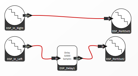
Delay Echo
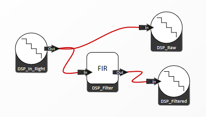
Filter Phase Locked Loop
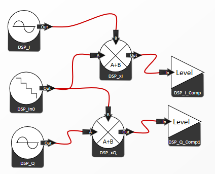
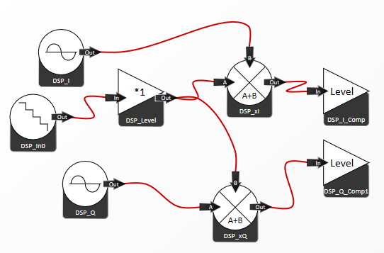
QPSK modulation Multiplex
Data flow program Flowcode control panel Signal generator with noise This program allows students to create a signal and noise generator that uses the Sysblocks rotary encoders to select the type of base signal, the amplitude and the frequency of the signal.


                          Data flow program                                                                           Flowcode control panel

                                                          AM demodulator
This program is a digital AM demodulator with four types of demodulation: envelope, phase, multiplier, unsynchronised multiplier.
Students make the choice of which demodulation system is used by making selections with an encoder input and the LCD display.


Data flow program

Flowcode control panel
Graphic equaliser
This program is a graphic equaliser which works by splitting the audio signal into separate bands then recombining them at the levels dictated by the sliders.
 Data flow program Flowcode control panel
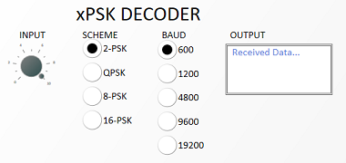
xPSK decoder demodulator
This program uses switches to select which xPSK decoding scheme to choose and which baud rate.
Data flow program Flowcode control panel
xPSK decoder demodulator
This program uses switches to select which xPSK decoding scheme to choose and which baud rate.


Data flow program

                                                                                Flowcode control panel


                                                              Audio effects system
                                          This program is a microcontroller based audio effects generator .