Using CAL Components
<sidebar>Sidebar: Flowcode Help Overview:ComponentCreation</sidebar>
Contents
Introduction
When creating a component for a specific sensor or other external IC you will often need to include some form of communications to talk to the device.
Communications and other key peripherals are wrapped up in a CAL (Code Abstraction Layer) component so we can simply use this in our component using the tricks listed below.
As an example we will go through creating an I2C based component using the I2C(CAL) component as the basis for communication.
If you are creating a component for a SPI or UART based device then use the applicable CAL for your device.
Adding CAL Component
To begin let's start by adding the CAL component you require for communication to your external device to our Flowcode project.
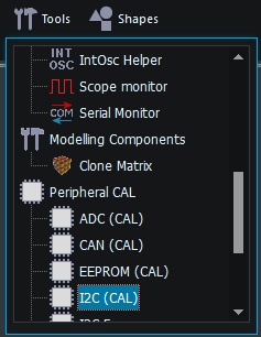
The CAL components can be found in the Tools -> Peripheral CAL component toolbar.
Exposing Properties
The CAL component has properties that are useful for setting up the peripheral as required by the user.
You probably want most of these settings to be available in your component so you have to expose them to be available when you export your project into a component.
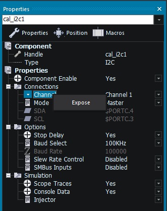
To expose a property simply select the CAL component on the panel or use the drop down menu at the top of the properties window.
Next using the properties window simply right click the property you wish to expose to the user and select Expose.
Common properties to expose include.
- Channel
- Bus Pins (and remap pins if available)
- Bus Speed control or Baud
- Simulation Options (Scope, Console, Injector)
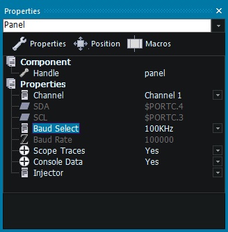
You can see which properties will be available to the user by clicking on a blank area of the component panel, or by choosing Panel from the drop down menu at the top of the Properties window.
If the property names look wrong then try right clicking the Properties in the Property window tree and ensure 'Show Titles' is ticked.
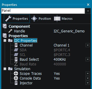
You may want to add categories to allow the properties to be tidied up. Properties can simply be dragged into the category you have created.
To create a new category simply right click the properties then select 'New category'.
Enter a name for the category in the window that appears. You can edit this name at any time by double clicking the category title in the properties tree.
Note properties need to be writeable and visible to be moved. In the example above I changed the Channel to Software to allow the pins to be moved and set the Baud to Custom to allow the Custom Baud property to be moved.
Hidden Properties
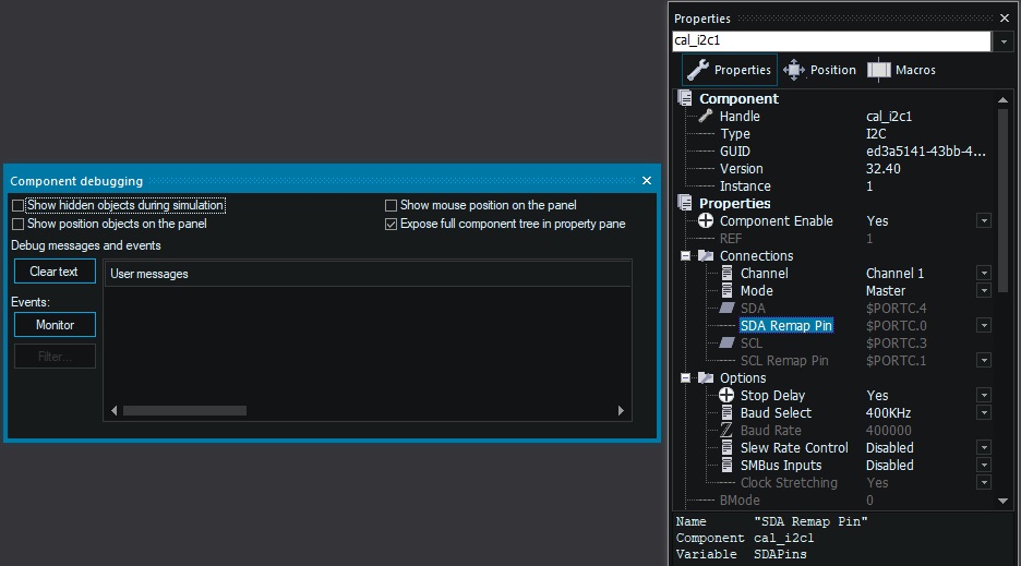
Some properties of the CAL component may be hidden by default. For example remappable pins are only shown when they are available on the selected target microcontroller.
To see all of the CAL components hidden properties use the View -> Component Debugger menu and tick the Expose full component tree check box. Then re-select the CAL component on the panel or using the drop down list at the top of the Properties window.
To move dynamic hidden properties into a category you have to make them available (writeable and visible), the easiest way is to select a chip with the available functionality.
Use the Build -> Project Options menu to select a different target device. The PIC 16F18877 is a good choice as it has all kinds of remappable peripherals supported as standard. PIC32 and ST-ARM devices are also a good choice.
Then make sure you set the channel to a hardware channel that supports the remappable functionality and the properties will become available to move.
Note. Remember to untick the Expose full component tree checkbox when you're done exposing properties to avoid incorrectly accessing hidden properties and to clean up the component interface.
Exposing Macros
The CAL component has macros that you may wish to directly expose to the user of your component.
Open the Project Explorer window and select the components tab, then right click any macros you want available and select Expose from the menu.
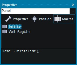
You can see which macros will be available to the user by clicking on a blank area of the component panel, or by choosing Panel from the drop down menu at the top of the Properties window and then selecting the Macros tab.
For this example we will not expose any of the CAL component macros as we will create our own macros that will call the CAL functionality.
Creating a Macro
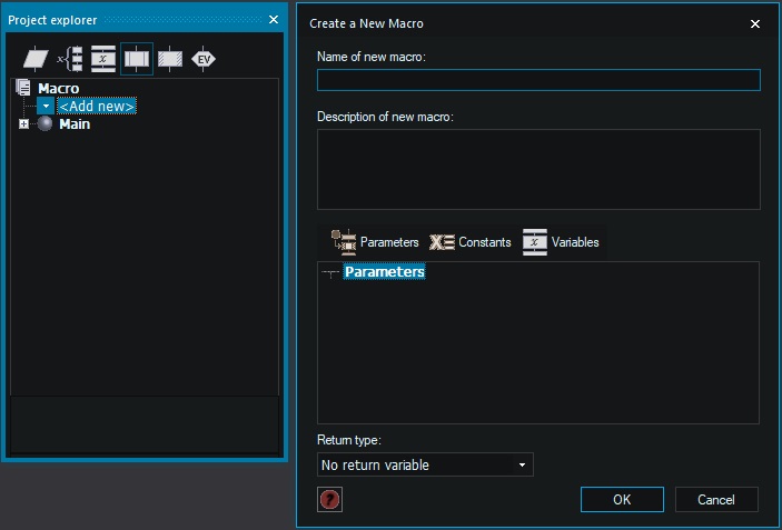
To create a component macro the user can call you simply create a normal macro as usual. Either use the Macro menu or the Macro tab of the Project Explorer window.
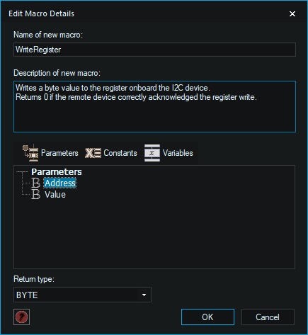
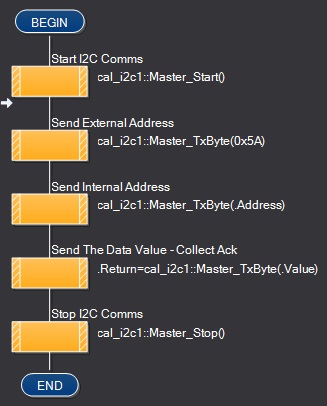
Here is a generic example, create a macro to write a value to a register with two parameters, a byte address and a byte value. These parameters would be based on the specifics of the device you're creating a component for. As we are using I2C we can detect if the remote device has acknowledged our request by using a return variable.
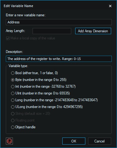
Give each of your parameters a helpful tooltip description to make it easier for the user of your component to know what is expected. The range of acceptable values can also be helpful. Also remember to add information about the return variable (if you're using one) in the macro's description field.
Inside the macro add the code to perform the functionality you require. Refer to the device datasheet for your sensor or IC to get the specifics of what is required. Example code can also be useful as you can follow the code, converting it into Flowcode icons as you go.
Here is a generic example for an I2C register write.
Add as many macros as you require. It's often best to start small e.g. being able to read or write a register on the device. Once you can do this you can confirm communications are working and then build up your component from there.
Initialise Macro
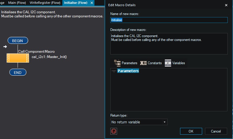
The CAL components often require initialisation. So simply create a new macro called Initialise to allow you to call the CAL initialise function.
Testing Your Macros
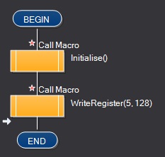
The Main macro is not included when exporting your component so we can use it to test our component code. You can either test using simulation or you can download to an embedded target to confirm your macros are functional.
Configuring Macros
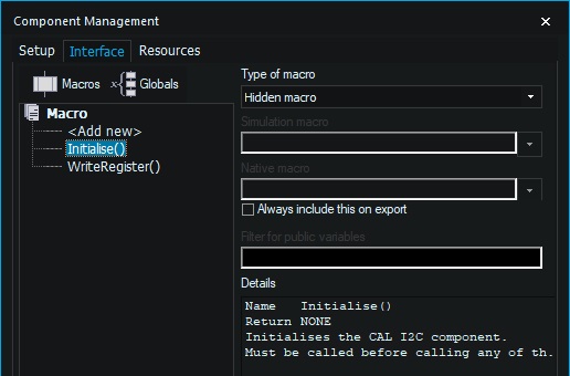
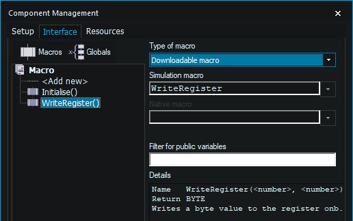
Any macros you have created also need to be exposed to the user of the component. You can do this using the File -> Component Configuration menu and selecting the Interface tab.
The macros we have created are shown in a list at the left hand side of the window.
Most macros you want the user of the component to be able to call will need to be set to Downloadable. This means it will be used for simulation and for embedded download. This is by far the most common type of component macro.
Any macros you have created that do not need to be called directly by the component user (private) can be left as hidden.
Click OK when you're done to exit the Component Management window.
You can see which macros will be available to the user by clicking on a blank area of the component panel, or by choosing Panel from the drop down menu at the top of the Properties window and then selecting the Macros tab of the Properties window.
Finishing Up
Before we export the component we need to do a number of small finishing steps to get the new component ready. First save your project in a meaningful location with a meaningful name so you can go back and re-export the modified component in future if needed.
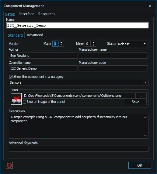
Next click on the File -> Component Configuration menu.
Setup Tab - Standard
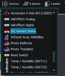
Give the component a Name, a Cosmetic Name, Assign a Category from the drop down menu.
Setup Tab - Advanced
If you have already created one component from your project file and want to create a new but different component then click Edit next to GUID and click New next to the GUID, this ensures you do not overwrite your previously exported component.
When you're done click OK.
Exporting the component
Next simply click the File -> Export menu to save the component as a .fcpx file. This file can be saved into the standard Flowcode components folder or you can create your own custom folder.
Flowcode 7
Components location : "C:\Program Files (x86)\Flowcode 7\Components"
Export somewhere with write access e.g. your desktop and then manually copy the file into the components folder using Windows explorer, you will need administrator permissions to write inside the Program Files (x86) folder.
Flowcode 8
Components location : "C:\ProgramData\MatrixTSL\FlowcodeV8\Components"
Export directly into the Components folder by copying and pasting the path into the filename field and hitting return.
Custom Location
Export directly to your own custom components folder.
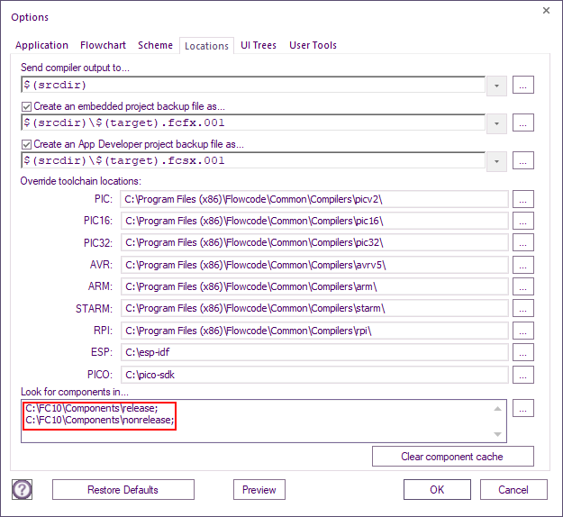
To use your own folder simply click on the View -> Global Options -> Locations Tab menu and add your custom folder location to the Look for components in... text field.
Using the component
The new component should now appear in Flowcode in the category you selected. Simply use the component as you would any other component.
You can always re-export your component from source if you need to make a change, add a new macro or fix a bug. Be sure to look after your component source files to allow you to re-export as required in future.
