Hello,
I've had a good poke around in the datasheet and looked at the remap registers and values being passed by Flowcode and so far it all appears to be correct.
You said this.
found that I can get pin 7 to produce the PWM when I assign to that pin, but not the others.
and then said this.
the PWM works perfectly when assigned to RB3. Assigning to RB7, RB8, or RB9 fails to produce a signal
The remap must be at least partially working as all outputs are by default set to null output.
If you create a simple program with a single PWM output which pins / timers are working. If you can somehow narow down the problem to a timer setting or pin setting then that might help.
If you look at the generated C code then you can see the PWM remap values being generated. Here is PWM channel 1.
Code: Select all
/*========================================================================*\
   Use :cal_pwm
       :Variable declarations
       :Macro function declarations
\*========================================================================*/
#define MX_PWM_REF1
#define MX_PWM_PRESCALE1 (1)
#define MX_PWM_PIN_1 (3)
#define MX_PWM_TYPE_1 (0)
#define MX_PWM_PORT_1 PORTB
#define MX_PWM_TRIS_1 TRISB
#define MX_PWM_CHANNEL_1 (1)


/*=----------------------------------------------------------------------=*\
   Use :cal_pwm
       :Supplementary defines
\*=----------------------------------------------------------------------=*/
#define MX_PWM
#define MX_PWM_REMAPPABLE
#define MX_PWM_RPOR_1 RPOR1bits.RP3R
#define MX_PWM_RPOC_1 18
#define MX_PWM_OCxCON
#define MX_PWM_TMR_1 1
These are the lines that handle the remapping.
#define MX_PWM_RPOR_1 RPOR1bits.RP3R
#define MX_PWM_RPOC_1 18
Here are the PWM channels
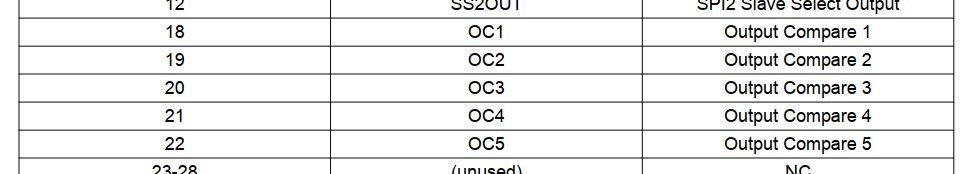
- RP_OC.jpg (31.35 KiB) Viewed 4187 times
Here are the output register bits, showing RP2R and RP3R inside register RPOR1.
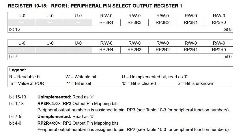
- RP_REG.jpg (84.05 KiB) Viewed 4187 times
And finally the RP pin assignment
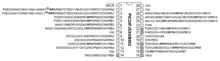
- RP_PIN.jpg (57.04 KiB) Viewed 4187 times
Hopefully with a simple test we can get to the bottom of what's going wrong for you.
Could it be something simple like opens or shorts on your PCB? Can you confirm with a multimeter.


