Choosing your Simulation Panel
Overview
In the Flowcode environment there are two types of panels that are used as a place to store components that are referenced by your program. In previous versions of Flowcode there were only two fixed panels available for the components so why did we move away from the two panels approach?
1) The 2D panels is used as a replacement for the dashboard panel used in previous versions of Flowcode. There are some differences still in that you can't currently zoom in and out.
2) The 3D system panel is used to allow features in Flowcode, such as mechanical based components or simulations. This allows us an area to build a system like we would in real life, in 3D. We can rotate around an object as well as being able to create multiple views so top, side, and perspective views can all be seen at once. We can also manipulate the camera for the first instance of the 3D system panel by using the camera simulation macros. This is useful for example for following a robot around as it moves through the simulated environment which could be a maze or obstacle course.
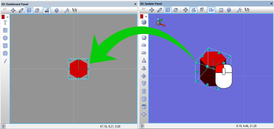
Components can be freely moved between panels by selecting the component and dragging between the panel windows. A component created by a user can only exist on one of the panel types to allow the user dragging on the component to choose which panel the component will live on.
Major Differences
The two panels have some very important differences which makes choosing which one to use in your project important.
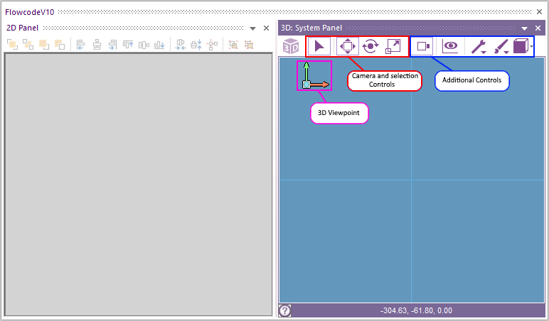
Pink: The 3D system has a 3D viewpoint where the camera angle can be rotated, while the 2D panel is restricted to a top down ‘2D’ view.
Red: Camera and selection controls are used to move and manipulate the camera of selected objects as required. See Camera Control for more details on their operation.
Blue: Additional controls are used to change the perspective, the way in which objects move through the simulation panel, background colours and more.
You can add as many 2D panels as you like and they all can be renamed.
Different Uses
| Circuit Level Users: | Electro-Mechanical Users: | Systems Designers: |
| We envisage users who are basically dealing with items which could be represented on a circuit board to only really require the 2D Panels. These users should not really need to construct 3D systems and the 2D Panels should be sufficient for their needs. Using only the 2D panels mimics the Flowcode v9 or less, panel usage. | For these types of projects we would envisage users requiring a combination of BOTH the 3D System Panel and the 2D Panels. Mechanical systems and parts can be modelled in the 3D System panel and the controlling elements of the system can be placed in the 2D Dashboard Panel. | Users who mainly utilise Flowcode for designing large systems will probably find most of their use from the 3D System Panel, however as for Electro-Mechanical users the 2D panels may prove useful for adding in controlling components to the system design. |
Examples:
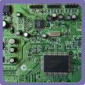
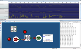 Example 1: DSP System: Since this is a circuit based problem we can use the 2D panels only.
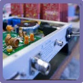
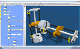 Example 2: Linear Actuator: Since this is a circuit based problem we can use the 2D panels only.
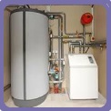
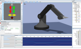 Example 3: Robot Arm: As an Electro-mechanical system we have our robot arm modelled in the 3D System Panel and the controls for this arm in our 2D panels.
Switching Components between Views:
Because the panels function exactly the same behind the scenes it is very quick and easy to transfer components from one view to the other. With 'Selection Mode' enabled, simply click and hold the object you want to transfer and drag it to the other panel.
In the example below we have dragged a hexagonal prism from the 3D System Panel to the 2D panels.
