Exercise - Expanding a Program
<sidebar>Sidebar: Taking Flowcode Further</sidebar> This exercise assumes you have created, tested and documented the program described in the exercise Documenting a Flowchart.
Because you have documented the flowchart properly, you can easily and accurately change the program as you know exactly how the program functions and what process it goes through.
You do not have to massively alter your program to make it more effective, sometimes a little change can make a big difference, simply adding and configuring one component can change the program to be much more effective and suitable for use elsewhere.
Contents
Load the Flowcode flowchart
- Open the flowchart called 'Lamp1.fcf' which you created earlier and documented in the exercise Documenting a Flowchart.
Enhancing a program
Now that you have a fully functioning program which is properly documented both by display names of icons and detailed comments, you can manipulate this program integrate it into another system, or expand the program further and turn it into your own expanded system, and even turn it into a full application.
We are going to expand our program to function as a set of traffic lights, to do this we are going to add 2 more LEDs and add to our 'Decision' icon which responds to when the switch is on to activate the traffic lights accordingly.
Add the LEDs
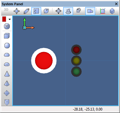
First of all, we are going to set up the System Panel and add two more LED components to expand the program.
- Add two LED components by using either of the following methods:
- Either copy and paste the current component on the System Panel to duplicate the component.
- Or add two more components by using the Components Toolbar.
Now position the LEDs accordingly on the System Panel.
- Move the LEDs to be aligned in a row on the Y axis.
- Ensure the original green LED component is at the bottom and that it is still connected to '$PORTB.0'.
Next change the colour and connection properties of the two new LEDs.
- Change the middle LED properties.
- Connect the LED to Port B Pin 1 by changing the 'Connection' property to '$PORTB.1'.
- Change the 'Color' property to yellow (00FFFF) using the colour selection window.
- Change the top LED properties
- Connect the LED to Port B Pin 2 by changing the 'Connection' property to '$PORTB.2'.
- Change the 'Color' property to red (000FF) using the colour selection window.
Expand the program
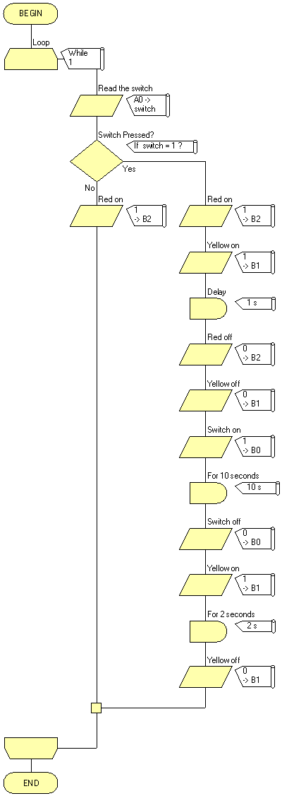
Now that the components are set up correctly, its time to configure the flowchart and expand the program. Firstly we need to set up the default state of the traffic lights to display only the red light when the switch is not pressed.
- Add an 'Input' icon to the 'No' section of the 'Decision' icon.
- Change the 'Display name:' to "Red on".
- Input the the value "1" into the 'Variable or value:' box.
- Set the 'Port:' connection to 'PORTB'.
- In the 'Output to:' section select 'Single Bit:' and change the pin to '2'.
- Click 'OK' to confirm the changes to the icon.
We are now going to set up the activation sequence of the traffic lights by configuring and expanding the 'Yes' section of the 'Decision' icon.
- Add 4 'Input' icons above the existing icons, then add a 'Delay' icon in-between the 4 'Input' icons.
- We will configure these icons top to bottom as follows:
- Change the 'Display name:' of the first 'Input' icon to "Red on".
- This icon is the same as the previous one we set up in the 'No' section of the 'Decision icon'.
- Send the value '1' to Port B, Pin 2.
- For the second 'Input' icon change the name to "Yellow on".
- Similarly send the value '1' to Port B but this time send it to bit (pin) 1
- Next is the 'Delay' icon.
- Change the name to "For 1 second".
- Input the value "1" into the 'Delay value or variable:' box.
- Change the unit to 'seconds'.
- Switch the first two (red and yellow) lights off to allow the last (green) light to show on its own which we programmed before.
- Alter the 'Input' icon after the 'Delay' icon.
- Change the 'Display name:' to "Red off".
- Send the value "0" to Port B, Pin 1 - this switches off the red light.
- Configure the next 'Input' icon, the last of the new icons we added.
- Name it "Yellow off".
- Send the value "0" to Port B, Pin 2 - this switches off the yellow light.
Next, the green light displays for 10 seconds before switching off, this is due to the icons we configured and programmed in the earlier exercises.
- Update the display names of the existing icons as follows:
- Replace the "Switch on" display name with "Green on".
- Replace the "Switch off" display name with "Green off".
- Under these icons add an 'Input' icon, followed by a 'Delay' icon and finally add the last 'Input' icon.
- Configure the first 'Input' icon.
- Change the 'Display name:' to "Yellow on".
- In the 'Variable or value:' box type "1".
- Change the 'Port:' to 'PORTB'.
- In the 'Output to:' section select 'Single Bit:' and change the value to '1'.
- Now configure the 'Delay' icon.
- Change the 'Display name:' to "For 2 seconds".
- Type "2" into the 'Delay value or variable:'.
- Change the unit to 'seconds'
- Finally configure the last 'Input' icon.
- Change the 'Display name:' to "Yellow off".
- In the 'Variable or value:' type "0".
- Change the 'Port:' to 'PORTB'
- In the 'Output to:' section select 'Single Bit:' and change it to '1'.
Final testing
- Save the flowchart.
- Run the simulation to test that it works.
- If you are going to further expand a program, or release it for public use, be sure to document the flowchart accordingly to explain the process and describe what affect it has on the components.
What Next?
Now you have effectively developed and expanded a program you can move on to other exercises and learn different areas, methods and techniques.
There are further exercises throughout the Flowcode Help section, you can also go to the Exercises section for similar articles with instructions to follow to demonstrate processes such as creating a component.

