IO Properties
Contents
Introduction
Most embedded components will require some form of connection to the real world. This is usually done via the standard input/output pins of the microcontroller.
You could simply use Input and Output flowchart icons to do this but this fixes the functionality to specific pins.
To allow the pin connections to be changed by the user we need a way to dereference the input/output commands from the pin connections.
This topic will deal with creating properties to allow your component macro code to interact with the microcontroller pins as specified by the user of the component.
For input/output pins connected to a communications bus or peripheral (ADC, PWM, I2C, SPI, UART) please see the Using_CAL_Components topic instead.
Single Digital Pin
The first type of pin connection we will look at is a single digital pin, this can be used for input or output purposes and is the most common type of pin connection.
Creating a property
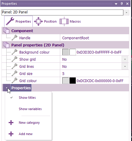
First click on a blank area of the 2D or 3D panels to select the root "Panel" object. You can also use the drop down menu at the top of the Properties window.
Open up the properties window and click the drop down arrow next to the Properties item in the window.
Select Add New from the menu.
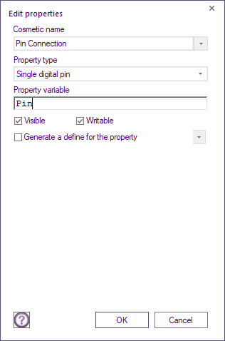
Give the property a cosmetic name, we have used Pin Connection
Select single digital pin from the drop down list
Give the property a property variable, we have used Pin
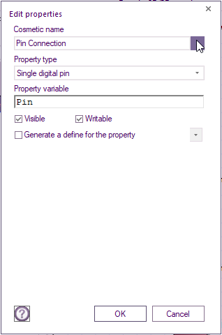
Next click the drop down arrow next to the cosmetic name.
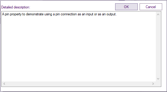
Enter a detailed description of what the pin will be used for.
This defines the property tooltip that is shown to inform the user the purpose of the property.
Click OK and OK again to close the Detailed Description and Edit Property windows.
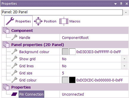
You should now have a new pin connection available on the properties window complete with tooltip.
Referencing the property
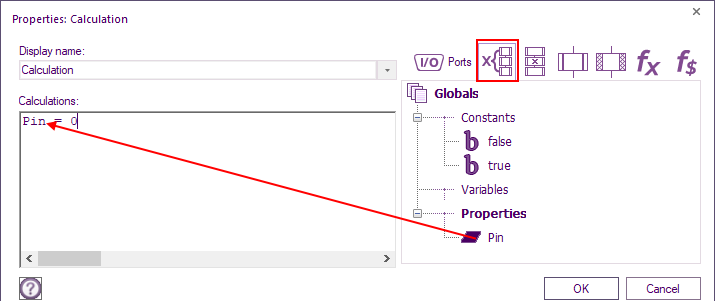
To reference the property simply use the variable name inside a calculation icon.
To output a logic low to the pin connection simply use an equals character to assign the value 0 to the pin.
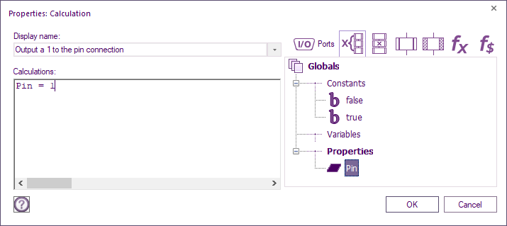
To output a logic high to the pin connection simply use an equals character to assign 1 to the pin.
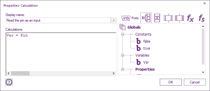
To read the logic level of an input voltage connected to the pin simply use an equals character to assign the pin to a variable.
Digital Port Byte
The next type of pin connection we will look at is a digital port byte, this can be used for input or output purposes and allows 8 pins from the same port byte to be utilized in a single command.
Creating a property
First click on a blank area of the 2D or 3D panels to select the root "Panel" object. You can also use the drop down menu at the top of the Properties window.
Open up the properties window and click the drop down arrow next to the Properties item in the window.
Select Add New from the menu.
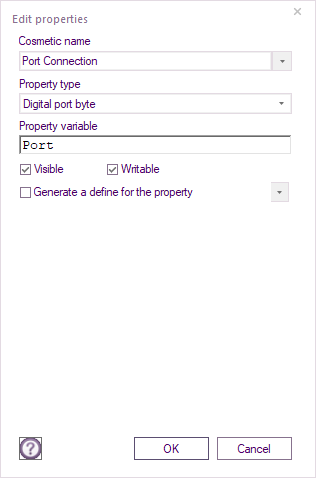
Give the property a cosmetic name, we have used Port Connection
Select digital port byte from the drop down list
Give the property a property variable, we have used Port
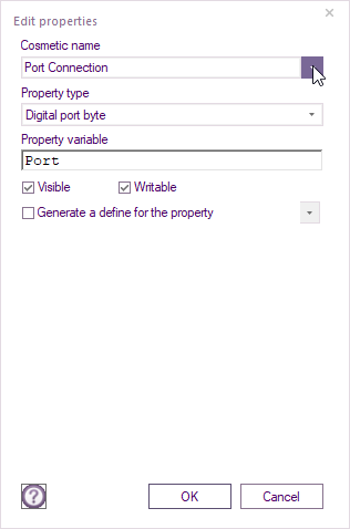
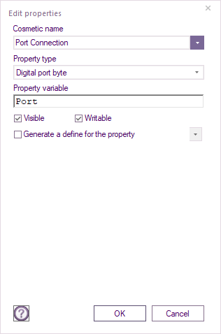
Next click the drop down arrow next to the cosmetic name.
Enter a detailed description of what the port will be used for.
This defines the property tooltip that is shown to inform the user the purpose of the property.
Click OK and OK again to close the Detailed Description and Edit Property windows.
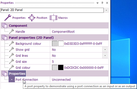
You should now have a new port connection available on the properties window complete with tooltip.
Referencing the property
To reference the property simply use the variable name inside a calculation icon.
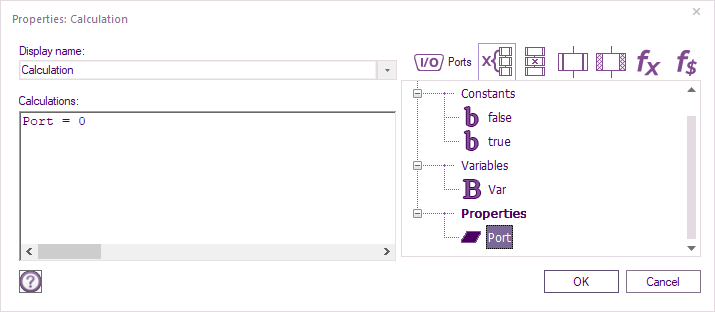
To output a logic low to the port pins simply use an equals character to assign the value 0 to the port.
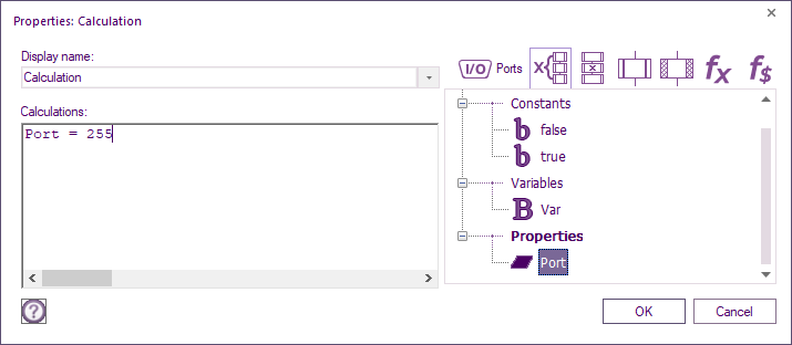
To output a logic high to the port pins simply use an equals character to assign 255 to the port.
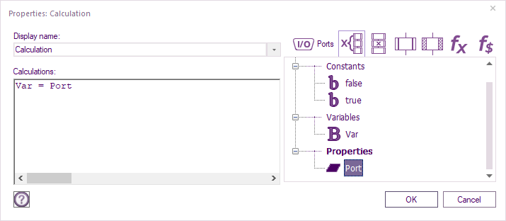
To read the logic level of an input voltage connected to the port pins simply use an equals character to assign the port to a variable.
Analog Inputs
There is a single analog pin property type to allow you to choose an analog input pin for use in a component. However this is not the best way to allow for a user selectable analogue input.
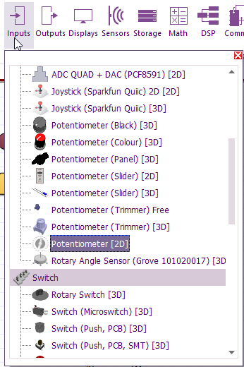
The best way is to start by adding an ADC component e.g. Potentiometer to your project as this will allow you to select a pin and bring across the code to allow you to read the voltage present on the pin.
Exposing Properties
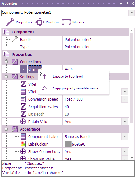
Select the Potentiometer component on the panel or select the Potentiometer1 component from the drop down menu at the top of the properties window.
Right click the properties you wish to expose to the user and select expose.
For analog inputs it is a good idea to expose the following.
- Channel - Allows you to specify the analog input pin
- VRef voltage - Allows you to specify the target microcontroller VCC or max ADC sample voltage
- VRef option - Allows the ADC max reference to be set or adjusted by the component user
- Conversion speed - Controls the speed of the ADC conversion and is related to accuracy
- Aquisition cycles - Amount of time to wait to pre-charge the ADC conversion capacitor to prevent channel bleed
- Retain Value - Allows the position of ADC component to be retained after project has been reloaded.
- Scope Traces - Allows the analogue voltages to be displayed on the data recorder window for simulation and displaying E-blocks Ghost ICT analog data.
See here for more info Customising_A_Component#Exposing_Properties
Sampling the analogue input
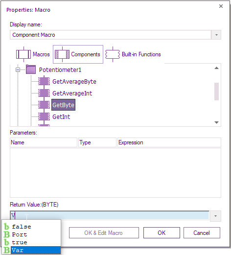
The analogue input is then sampled the usual way by calling the Potentiometer1 component macros.
You can either call the component macros directly in your component's macros or you can expose the adc_base1 component macros for the user to call.
See here for more info Customising_A_Component#Exposing_Macros
