Exercise - Using Interrupts
<sidebar>Sidebar: Flowcode Exercises:Ex1</sidebar> Interrupts are a way of grabbing the microcontroller's attention immediately.
They are very widely used, both in microcontrollers and microprocessors. For example, the keyboard and mouse in your computer probably use interrupts to talk to the CPU.
They can also be used to save energy. In many battery-powered applications, the microcontroller is 'put to sleep' when inactive, and so requires little energy. An interrupt is used to 'awaken' the controller, and bring it back into operation, when needed.
This exercise shows how to use an interrupt to sense when a switch is closed, (an external interrupt).
Contents
Polling vs interrupt
The microcontroller is often connected to a large number of peripheral input devices - switches, sensors, memory, timers etc. There are two broad ways in which one of these devices can be serviced by the microcontroller:
- polling - each device is 'asked' in turn if it has data to transfer to the controller;
- interrupts - allow the device to interrupt the task being carried out by the controller.
The exercise aims to show the difference between polling and using interrupts.
The system
This exercise sets up a system with LEDs controlled by two switches:
- Switch 1 is polled by the program, at regular intervals.
- Switch 2 initiates an interrupt.
- Switch 1 is polled by the program, at regular intervals.
The polled switch, switch 1, is checked at regular (and predictable) intervals - every six seconds in this example.
Switch 2 is connected so that as soon as it operates, the processor stops what it is doing and jumps to the Interrupt Service Routine (ISR). In the process, the return address is stored, so that at the end of the ISR, the processor can return to where it left the main program. In Flowcode, the ISR takes the form of a macro, configured like any other.
The flowchart
The flowchart sequence:
- Check if switch 1 is pressed.
- If it isn't, make the red LED flash slowly.
- If it is, make the yellow LED flash slowly.
- Go back to the beginning and repeat the process.
- Whenever switch 2 is pressed, immediately make both LEDs flash quickly ten times and then go back to the main program.
The main program
- Start a new Flowcode flowchart, using the default microcontroller.
- Make sure that the System Panel is visible. If necessary, click on View and then select 'System Panel' a check-box will appear next to the option when enabled.
- Drag and drop a 'Loop' icon between the BEGIN and END icons.
- Inside the loop, drag and drop an 'Input' icon from the Icons toolbar.
- Drag and drop a 'Decision' icon after the 'Input' icon.
Next, add icons to control what happens when switch is not pressed, (and so the program follows the 'No' branch):
- Drag and drop an 'Output' icon in the 'No' branch.
- This icon is going to turn the red LED on.
- Drag and drop a 'Delay' icon after the 'Output' icon.
- This will keep the LED on for three seconds.
- Follow it with another 'Output' icon.
- This icon is going to turn the LED off.
- Add a second 'Delay' icon next.
- This will keep the LED off for three seconds.
The program then loops back and checks the state of the switch again.
Next, add icons to control what happens when switch is pressed, and so the program follows the 'Yes' branch:
- Drag and drop an 'Output' icon in the 'Yes' branch.
- Drag and drop a 'Delay' icon after the 'Output' icon.
- Follow it with another 'Output' icon.
- Add a second 'Delay' icon next.
The program then loops back, as before, and checks the state of the switch again.
Add switch 1 and the LEDs
- Locate the 'Inputs' toolbox, and click on the down arrow next to the switch labelled 'Toggle Metal PCB'.

- Click on the 'Add to system panel' option.
- Configure its properties so that it is connected to Port B, bit 1.
- Locate the 'Outputs' toolbox, and click on the down arrow next to the 'LED Array' label.

- Click on the 'Add to system panel' option.
- Click on one, and configure its properties as follows
- set the 'Count' property to "2", to give two LEDs in the array;
- set the colour of LED0 to red, and that of LED1 to yellow.
- LED0 will light when Port A is sent value '1', and LED1 will light when Port A is sent value '3';
- check that the 'Connections' property shows that it is connected to Port A.
Double click on each icon in the flowchart and configure it as shown in the following images:
- Configuring the icons

Turn the red LED on
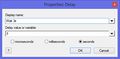
Three seconds delay

Turn the LEDs off
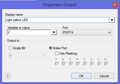
Turn on the yellow LED
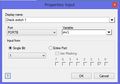
Configure switch 1
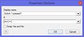
Configure the decision icon


To see a larger version, double click on the image.
Simulate the flowchart to make sure that the LEDs behave as expected.
Add switch 2

- Add a second 'Toggle Metal PCB' switch to the system panel.
- Configure its properties so that it is connected to Port B, bit 0 - the hardware interrupt bit.
- Drag and drop an interrupt icon
 between 'BEGIN'and the upper loop icon, (although it will work anywhere in the flowchart.)
- Double click on the icon, and configure it as shown opposite.
- The next task is to create the ISR. Click on the 'Create New Macro...' button.

- The 'Create a New Macro' dialogue box opens.
- Give the macro the name "flash_fast".
- Click on OK.
- In the 'Properties:Interrupt' dialogue box, click on the 'OK & Edit Macro' button.
- Create the flowchart shown opposite for the macro.
- Sending value '3' (=00011 in binary,) to Port A switches on both LEDs.
The main flowchart
Your flowchart should now be set up to resemble the image below:

Test the system
Earlier, you tested the effect of switch 1 on the LEDs. Now you can test the effect of switch 2 as well.
- Run the simulation, and confirm the action of switch 1 on the LEDs.
- While Flowcode is simulating a three second delay, toggle switch 2 on and off.
- The three second simulationshould stop, mid-delay, and both LEDs should flash quickly, ten times, as specified in the ISR.
- After this, the microcontroller resumes the main program from where it left off, the three second delay.
- Repeat the tests until you are happy with the way the system operates.
Download the exercise
You can download the file created by this exercise and open it in Flowcode to identify errors in your program/file or you could also download the file to skip to the next exercise.
- To download the file, click on the link below and then either:
- Click on the file name.
- Right click the file name and select 'Save link as...' or 'Save target as...' (depending on your browser).