|
Electronic circuits and components * Course Index * Introduction * About the Author * About this Course * Feedback * Course Navigation * How to use this Course * TINA * Locktronics Fundamentals * Introduction: Fundamentals * Units and Multiples * Electricity * Electronic Principles * Electrical Circuits * Alternating Current * Assessment: Fundamentals Passive Components * Introduction: Passive Components * Resistors * Capacitors * Inductors * Transformers * Batteries, Fuses, Lamps and Switches * Assessment: Passive Components Semiconductors * Introduction: Semiconductors * Diodes * Transistors * Logic Gates * Assessment: Semiconductors Passive Circuits * Introduction: Passive Circuits * Series and Parallel Connections * Kirchoff's Laws * Potential and Current Dividers * Passive Time Variant Circuits * Assessment: Passive Circuits Active Circuits * Introduction: Active Circuits * Power Supply Circuits * Operational Amplifier Circuits * Transistor Amplifier Circuits * 555 Timer Circuits ## Introduction: 555 Timer ## Astable Pulse Generator ## Monostable Pulse Generator * Assessment: Active Circuits Parts Gallery * Introduction: Parts Gallery * Passive Component Images * Semiconductor Images * Other Images * Quizzes |
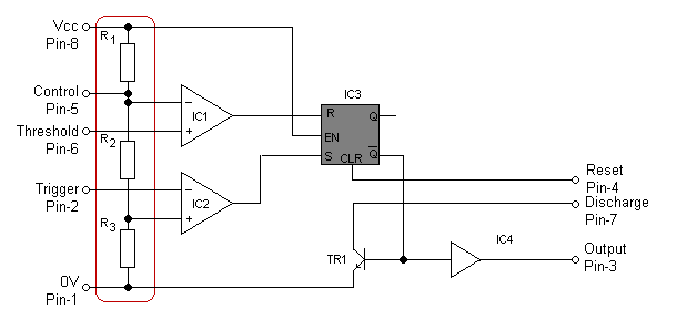
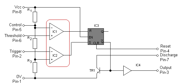
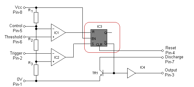
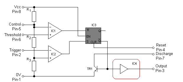
(:Summary:Contains the 'action' links (like Browse, Edit, History, etc.), placed at the top of the page, see site page actions:) (:comment This page can be somewhat complex to figure out the first time you see it. Its contents are documented at PmWiki.SitePageActions if you need help. :) * Print (:comment (:if group Site,SiteAdmin,Cookbook,Profiles,PmWiki*:) (:comment delete if and ifend to enable backlinks:) * %item rel=nofollow class=backlinks accesskey='$[ak_backlinks]'% [[{*$Name}?action=search&q=link={*$FullName} | $[Backlinks] ]] (:ifend:) :) * Login Introduction: 555 Timer<^< 555 Timer Circuits | Course Index | Astable Pulse Generator >^>(:nl:) The 555 timer is without doubt one of the most versatile integrated circuit chips ever produced. Not only is it a neat mixture of analogue and digital circuitry but its applications are virtually limitless in the world of digital pulse generation. In order to understand how timer circuits operate, it is worth spending a few moments studying the internal circuitry of the 555 even though at this stage you may not have covered sufficient material to understand all aspects of the 555 operation. (R-S bistables are covered in Digital Electronics). Essentially, the 555 comprises two operational amplifiers (used as comparators) together with an R-S bistable logic element. In addition, an inverting buffer is incorporated so that a considerable current can be delivered to a load.
| |
(:Summary: Website page footer:)
Print - (:comment (:if group Site,SiteAdmin,Cookbook,Profiles,PmWiki*:) (:comment delete if and ifend to enable backlinks:) %item rel=nofollow class=backlinks accesskey='$[ak_backlinks]'% [[{*$Name}?action=search&q=link={*$FullName} | $[Backlinks] ]] (:ifend:) :) Search - Login
Page last modified on August 23, 2011, at 09:46 AM